
A BLDC motor looks simple from the outside — a cylindrical housing with a shaft on one end and wires on the other. Inside, however, is a precisely engineered system of permanent magnets, copper windings, Hall effect sensors and bearings working together. Understanding the internal construction and wiring helps you select the right motor, connect it correctly, and troubleshoot problems when they arise. This guide uses our standard motor range as examples.
BLDC Motor Internal Construction
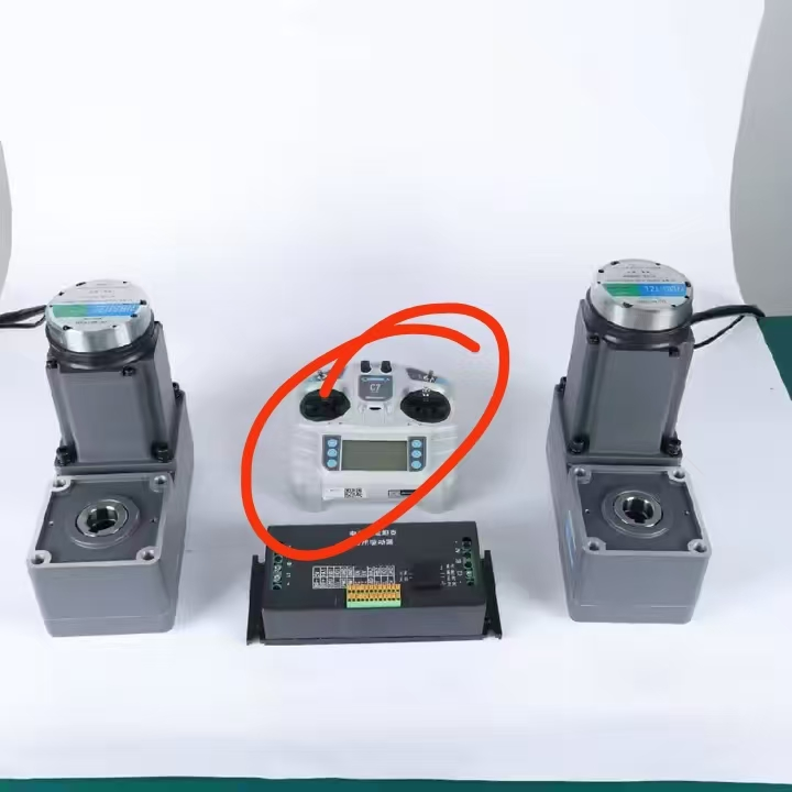
Every brushless DC motor consists of four major components:
1. Stator (Stationary Winding Assembly)
The stator is the fixed part of the motor. It consists of a laminated silicon steel core with slots, wound with copper wire to form electromagnetic coils. In a 3-phase BLDC motor, there are three sets of coils arranged at 120-degree electrical intervals. When current flows through a coil pair, it creates a magnetic field that attracts or repels the rotor magnets, producing rotation.
Stator quality is defined by the silicon steel grade (higher grades like 35WW300 have lower core losses), the copper fill factor (how tightly the wire fills the slots — our motors achieve 55-65%), and the winding insulation class (Class B at 130C or Class F at 155C).
2. Rotor (Permanent Magnet Assembly)
The rotor carries NdFeB (neodymium iron boron) permanent magnets bonded or mechanically fixed to a steel core on the motor shaft. The number of magnet poles determines the motor's speed-voltage constant (Ke) and torque constant (Kt). Common configurations:
- 4-pole: Higher speed, lower torque per amp. Typical for small motors (42-60mm).
- 8-pole: Balanced speed and torque. Standard for medium motors (80-104mm).
- 10-pole: Lower speed, higher torque density. Common for large motors (120-130mm).
The magnet arrangement can be surface-mounted (SPM) or interior (IPM). Our standard motors use surface-mounted NdFeB magnets with N42SH grade, providing good torque density and thermal stability up to 150C.
3. Hall Effect Sensors
Three Hall effect sensors are mounted on the stator PCB at 120-degree electrical intervals. They detect the rotor magnet position and output digital signals (high/low) that tell the controller which phase pair to energize next. The Hall sensor commutation sequence has 6 steps per electrical cycle, producing the characteristic trapezoidal current waveform that gives BLDC motors their name.
Hall sensors operate on 5V DC (some controllers provide 12V — check compatibility). They output 3 digital signals: Hall A, Hall B and Hall C. The 6-step commutation sequence is:
| Step | Hall A | Hall B | Hall C | Phase Energized |
|---|---|---|---|---|
| 1 | 1 | 0 | 1 | U+, V- |
| 2 | 1 | 0 | 0 | U+, W- |
| 3 | 1 | 1 | 0 | V+, W- |
| 4 | 0 | 1 | 0 | V+, U- |
| 5 | 0 | 1 | 1 | W+, U- |
| 6 | 0 | 0 | 1 | W+, V- |
4. Bearings and Housing
The shaft rotates on two ball bearings — one at the drive end (DE) and one at the non-drive end (NDE). Our standard motors use 6200-series or 6300-series deep groove ball bearings (C&U or HRB brand) with grease lubrication rated for 20,000+ hours at rated speed. Premium options include NSK or SKF bearings for extreme-reliability applications.
The housing is machined aluminum alloy (6061 or similar) for motors up to 104mm, and cast aluminum or steel for 120mm+ frames. IP54 sealing is achieved with rubber O-rings at the shaft exit and end cap joints. IP65 adds a lip seal on the shaft and additional gaskets.
Wiring Diagram: Motor to Controller
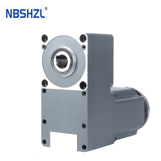
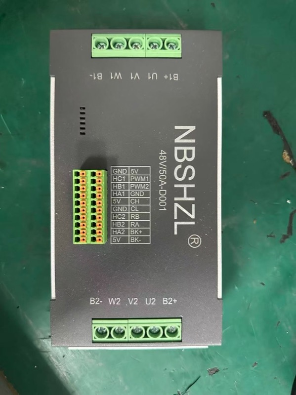
Connecting a BLDC motor to its controller requires two sets of connections: power (3 phase wires) and signal (Hall sensor wires).
Power Connections (3 Wires)
The three motor phase wires — typically color-coded red (U), yellow (V), blue (W) — connect to the controller's three motor output terminals. These carry the main motor current (rated current ranges from 2A for a 60W motor to 80A for a 3kW motor at 48V).
Wire gauge matters. For motors up to 500W at 48V, 18 AWG (0.75mm2) is sufficient. For 500W-1,500W, use 14 AWG (2.5mm2). For 1,500W-3,000W, use 10 AWG (6mm2) or larger. Undersized wire causes voltage drop and heat, reducing motor performance.
Hall Sensor Connections (5 Wires)
The 5-wire Hall sensor cable connects to the controller's Hall input:
- Red: VCC (+5V power supply from controller)
- Black: GND (ground reference)
- Green: Hall A signal
- White: Hall B signal
- Yellow: Hall C signal
Note: Wire colors may vary between manufacturers. Always verify with the motor's datasheet or pinout diagram. Our motors include a labeled wiring diagram with every shipment.
Optional: Encoder Connections (4-6 Wires)
If the motor includes an incremental encoder (1,000 PPR standard), the encoder cable has:
- VCC: +5V (shared with Hall sensors or separate)
- GND: Ground
- A / A-: Channel A (and inverted, for differential output)
- B / B-: Channel B (and inverted)
- Z / Z-: Index pulse (one pulse per revolution)
Looking for a reliable BLDC motor supplier? Get a sample motor shipped in 7 days.
Request a Quote →Star vs Delta Winding Configuration
BLDC motors can be wound in two configurations, each affecting performance:
Star (Y) Connection
One end of each phase winding connects together at a common neutral point. The phase voltage is 1/sqrt(3) of the line voltage (about 58%). Star winding provides:
- Higher torque at low speed
- Lower starting current
- Easier sensorless startup
- Standard for most BLDC motors under 1kW
Delta Connection
Phase windings connect end-to-start in a triangle — no neutral point. Each phase sees the full line voltage. Delta provides:
- Higher speed capability (approximately 1.73x the star-connected speed at the same voltage)
- Higher power output from the same motor frame
- Higher starting current — requires a controller with higher current rating
- Used for high-speed or high-power-density applications
Our standard: All Shenghe Zhilian BLDC motors ship with star (Y) winding unless delta is specifically requested. For AGV, machinery mover and transport applications, star winding is almost always the correct choice because low-speed torque and smooth startup are more important than maximum speed.
Common Wiring Mistakes and Troubleshooting
From our technical support experience, these are the most frequent connection errors:
- Motor spins in the wrong direction: Swap any two phase wires (e.g., U and V) AND swap the corresponding Hall sensor wires (Hall A and Hall B). Both must be swapped together — swapping only the phase wires without the Hall wires will cause erratic operation.
- Motor vibrates but does not rotate: Hall sensor wiring is incorrect. Verify VCC is 5V (not 12V or 24V — this will burn out the Hall sensors), and check that Hall A/B/C are connected to the correct controller inputs.
- Motor runs but with cogging/jerking: One Hall sensor may be faulty, or the commutation sequence is wrong. Measure each Hall output with an oscilloscope while slowly rotating the shaft by hand — all three should produce clean square waves with 120-degree phase shift.
- Motor overheats at low load: Check for voltage mismatch. Running a 24V motor on 48V will double the current draw and generate excessive heat. Always verify the motor's voltage rating matches the controller output voltage.
Frequently Asked Questions
How many wires does a BLDC motor have?
A standard 3-phase BLDC motor has 3 power wires (phases U, V, W) plus 5 Hall sensor wires (VCC 5V, GND, Hall A, Hall B, Hall C) — 8 wires total for a basic configuration. Adding an encoder adds 4-6 wires, and an electromagnetic brake adds 2 more. A fully equipped motor may have 14-16 wires.
What are Hall sensors in a BLDC motor and why are they important?
Hall sensors are small magnetic field detectors mounted on the stator at 120-degree electrical intervals. They detect rotor position and tell the controller which phase to energize next. Without them, the motor cannot start reliably under load. Sensorless control works at higher speeds but Hall sensors are required for reliable low-speed operation and loaded startup.
What is the difference between a BLDC motor and a brushed DC motor?
In a brushed motor, windings are on the rotor and commutation is mechanical via carbon brushes. In a BLDC motor, windings are on the stator and magnets are on the rotor — commutation is electronic. BLDC motors have no wearing parts except bearings, giving 5-10x longer service life (20,000+ hours vs 2,000-5,000 hours).
How do I connect a BLDC motor to a controller?
Connect the 3 phase wires (U, V, W) to the controller's motor outputs. Connect the 5 Hall sensor wires to the Hall input (VCC to 5V, GND to GND, Hall A/B/C to corresponding inputs). If the motor runs in the wrong direction, swap any two phase wires AND the corresponding two Hall wires together.
What does star vs delta winding mean for performance?
Star (Y) winding gives higher torque at low speed and lower starting current — standard for most BLDC motors under 1kW. Delta winding gives higher speed and power density but lower starting torque and higher current draw. Most industrial BLDC motors use star winding unless specifically requested otherwise.
Need Wiring Support or a Custom Configuration?
Our engineers provide wiring diagrams, connection guidance and controller configuration support for every motor we ship. Tell us about your application and we will help you get the right setup.