
Torque, speed and power are the three pillars of motor selection. Understanding how they relate to each other — and how to derive them from your mechanical load — is the difference between a motor that runs reliably for years and one that burns out in the first month. This guide covers the fundamental calculations our engineers use daily when specifying BLDC drive systems for transport equipment, AGVs and industrial machinery.
The Three Fundamental Relationships
Every electric motor obeys three core equations. These apply to all motor types — BLDC, AC induction, stepper — but we will use BLDC-specific values for our examples.
1. Torque-Power-Speed Relationship
P = T x omega, where P is power in watts, T is torque in N.m, and omega is angular velocity in rad/s. Since most datasheets use RPM rather than rad/s, the practical form is:
T (N.m) = 9.55 x P (W) / n (RPM)
This is the single most important formula in motor selection. It tells you: for a given power, increasing speed decreases torque, and vice versa. A 500W motor at 3,000 RPM produces 1.59 N.m. The same 500W motor at 1,500 RPM produces 3.18 N.m — twice the torque at half the speed.
2. Linear Force to Rotational Torque
For wheeled equipment, you need to convert linear force at the ground contact into rotational torque at the wheel shaft:
Twheel (N.m) = F (N) x r (m)
Where F is the total traction force and r is the wheel radius. With a 200mm diameter wheel (r = 0.1 m) and 500 N total force: Twheel = 500 x 0.1 = 50 N.m.
3. Linear Speed to Rotational Speed
nwheel (RPM) = (v x 60) / (pi x D)
Where v is linear velocity in m/s and D is the wheel diameter in meters. At 1.0 m/s with a 200mm wheel: n = (1.0 x 60) / (3.14159 x 0.2) = 95.5 RPM.
Calculating Load Forces
The total force your motor must overcome depends on what resistance the load presents. For transport equipment (trolleys, AGVs, machinery movers), there are four force components:
| Force Component | Formula | Typical Values |
|---|---|---|
| Rolling Resistance | F = M x g x Crr | Crr = 0.01-0.04 (wheel/floor dependent) |
| Gradient | F = M x g x sin(theta) | 5% grade = 490 N per 1,000 kg |
| Acceleration | F = M x a | a = 0.3-1.0 m/s2 typical |
| Wind / External | Application-specific | Usually negligible indoors |
Looking for a reliable BLDC motor supplier? Get a sample motor shipped in 7 days.
Request a Quote →Worked Example: Battery-Powered Machinery Mover
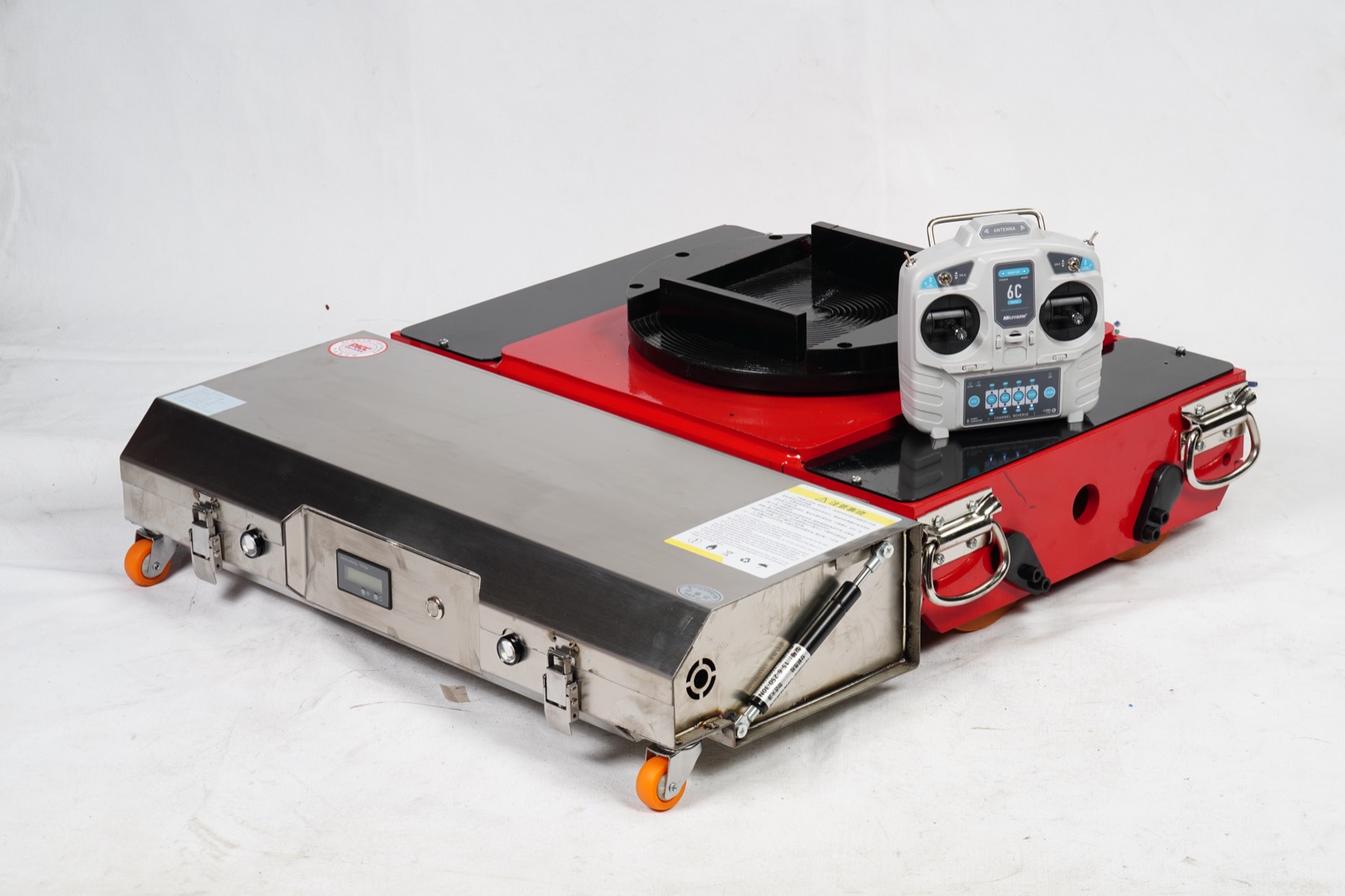
Let's size a drive motor for a powered machinery mover — one of the most common applications for our BLDC drive systems.
Requirements:
- Maximum load: 5,000 kg (machine weight on castors transferred to mover)
- Mover chassis weight: 300 kg
- Travel speed: 0.5 m/s (walking pace)
- Drive wheel diameter: 250mm
- Maximum gradient: 3% (workshop ramp)
- Floor surface: Smooth epoxy concrete
Step 1 — Forces:
- Rolling resistance: 5,300 kg x 9.81 x 0.015 = 780 N
- Gradient (3%): 5,300 x 9.81 x 0.03 = 1,559 N
- Acceleration (0.3 m/s2): 5,300 x 0.3 = 1,590 N
Step 2 — Torque at each wheel (dual-drive):
- Continuous (flat): 780 / 2 x 0.125 = 48.75 N.m per wheel
- Peak (slope + accel): (780 + 1,559 + 1,590) / 2 x 0.125 = 245.6 N.m per wheel
Step 3 — Wheel speed:
n = (0.5 x 60) / (pi x 0.25) = 38.2 RPM
Step 4 — Motor power (per motor, 75% efficiency):
- Continuous: (780 / 2 x 0.5) / 0.75 = 260 W
- Peak: (3,929 / 2 x 0.5) / 0.75 = 1,310 W
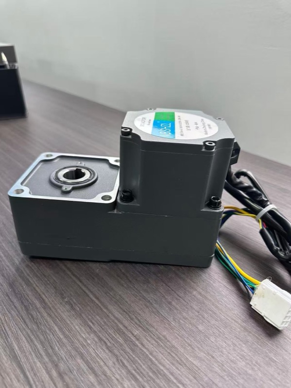
Selection: Two BL-120 L-type geared motors at 750W rated power, 48V, with 80:1 worm gear ratio. The worm gear provides self-locking for slope holding, and the 750W rating allows 2x peak (1,500W) for short-duration slope and acceleration loads. Add a 24V electromagnetic brake (15 N.m) for fail-safe parking.
Gearbox Efficiency: The Hidden Factor
Gearbox efficiency is often overlooked but it significantly impacts motor sizing. Here are typical efficiency ranges for the gear types we manufacture:
| Gear Type | Efficiency per Stage | Typical Ratios | Self-Locking? |
|---|---|---|---|
| Helical (R-type) | 92-96% | 3:1 to 100:1 | No |
| Worm gear (L-type) | 40-85% (ratio dependent) | 10:1 to 100:1 | Yes (above ~30:1) |
| Planetary | 90-95% | 3:1 to 512:1 (multi-stage) | No |
Note that worm gear efficiency varies dramatically with ratio. At 10:1, efficiency can be 80-85%. At 60:1, it drops to 50-60%. This is the trade-off for self-locking capability — the worm gear's inherent friction that prevents back-driving is the same friction that reduces forward efficiency. For high-efficiency applications, use helical or planetary gears with an external brake.
Thermal Considerations
Motor power rating is ultimately a thermal limit, not an electromagnetic one. A BLDC motor can produce far more torque than its nameplate rating — but only for a short time before the winding temperature exceeds the insulation class limit (typically 130C for Class B insulation).
Key thermal rules for motor selection:
- Continuous duty (S1): Motor operates at rated load indefinitely. Size for this if the load is constant (e.g., conveyor drive).
- Intermittent duty (S2/S3): Motor operates in on/off cycles. Typical for AGVs and movers — 2 minutes run, 1 minute stop. You can use a smaller motor for intermittent duty because the off-period allows cooling.
- Peak overload: 2-3x rated torque for 10-30 seconds. Acceptable for startup, acceleration and short slope climbing. Our controllers have thermal protection to cut power before the motor overheats.
Frequently Asked Questions
What is the formula for motor torque?
Motor torque T (N.m) = 9.55 x P (W) / n (RPM). For example, a 500W motor at 3,000 RPM produces T = 9.55 x 500 / 3,000 = 1.59 N.m at the motor shaft. After a 30:1 gear reducer (assuming 85% efficiency), the output torque becomes 1.59 x 30 x 0.85 = 40.5 N.m.
How do I convert between motor power in watts and horsepower?
1 horsepower (HP) = 746 watts. So a 750W BLDC motor is approximately 1 HP, and a 1,500W motor is approximately 2 HP. In metric specifications, kW is standard: 1 kW = 1.34 HP. Our motor range covers 15W (0.02 HP) to 3,000W (4 HP).
What is the difference between rated torque and peak torque?
Rated (continuous) torque is the torque the motor can deliver indefinitely without overheating. Peak torque is 2-3x the rated torque and can only be sustained for short periods (typically 10-30 seconds) before thermal limits are reached. For sizing, use rated torque for your continuous operating point and peak torque only for transient loads like acceleration or slope climbing.
How does gear ratio affect torque and speed?
A gear reducer multiplies torque and reduces speed by the gear ratio. A 30:1 ratio means the output torque is 30x the motor torque (minus gearbox losses, typically 5-15% per stage), and the output speed is 1/30th of the motor speed. For example, a motor at 3,000 RPM with 1.59 N.m through a 30:1 reducer gives approximately 100 RPM at 40.5 N.m (at 85% efficiency).
How do I calculate the power needed to move a load on wheels?
Power (W) = Force (N) x Velocity (m/s) / Efficiency. The force includes rolling resistance (mass x g x Crr), gradient force (mass x g x sin(angle)), and acceleration force (mass x acceleration). For a 2,000 kg load on flat concrete at 1 m/s with 75% drivetrain efficiency: P = (2,000 x 9.81 x 0.02 x 1.0) / 0.75 = 523W.
Related Engineering Guides
- How to Size a BLDC Motor for AGV Applications — step-by-step torque and power sizing for automated guided vehicles
- BLDC Motor for Machinery Movers — drive sizing for 1-50 ton electric movers
- 24V vs 48V BLDC Motor — voltage selection affects current draw and cable sizing
- Planetary Gearbox for BLDC Motors — gear ratio calculation and efficiency data
- BLDC Motor Controller Selection Guide — matching controllers to motor specifications
- Tug AGV Drive System Guide — motor sizing for autonomous towing vehicles
- AGV Tug BLDC vs AC Motor — efficiency, torque & cost comparison for tug drives
Need Help With Your Torque Calculation?
Share your load requirements — weight, speed, wheel size and environment — and our engineers will run the calculations and recommend a matched drive system.