
Most AGV drive wheel problems we are asked to fix are not motor problems. The customer sized the motor correctly, the datasheet torque is comfortably above the calculated requirement, and the vehicle still spins its wheels on a ramp or drifts off its path under load. The cause is almost always the same: torque was calculated, but the traction limit was not. This guide walks through both calculations, then covers the wheel, gearbox, brake and encoder decisions that follow from them.
Quick Answer
- Two calculations, not one. Size the motor from tractive force and check that the vertical load on the drive wheel can transmit it: Fmax = μ × N.
- The formula: F = m·g·(fr + sinθ) + m·a, then Twheel = F × r ÷ number of driven wheels, then Tmotor = Twheel ÷ (i × η).
- Slip is a weight problem. A differential AGV with four casters often puts only 25–35% of its weight on the drive wheels. Spring preload, not a bigger motor, fixes it.
- Wheel material follows the floor. PU 92–95 Shore A on epoxy; rubber 65–75 Shore A on rough, wet or outdoor concrete.
- Budget: $180–$320 for a 250 W / 150 mm assembly, $320–$600 for 500–750 W / 200 mm, $600–$1,200 for 1–2 kW / 250–300 mm, FOB Ningbo at 50–100 pcs.
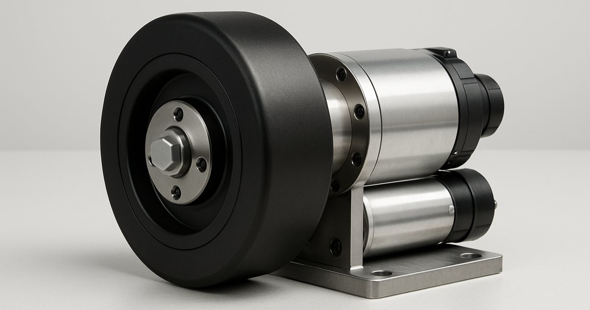
What Is in an AGV Drive Wheel Assembly?
A drive wheel assembly (also called a drive unit, traction unit or wheel drive) is the complete subsystem that converts DC bus power into motion at the floor. Buying it as one matched assembly rather than as loose parts matters more than most first-time builders expect, because the mounting interfaces, shaft fits and brake voltage have to agree with each other.
| Component | Function | Typical spec for a 1–1.5 t AGV |
|---|---|---|
| BLDC motor | Torque source | 500–750 W, 48 V, 3,000 rpm, IP54–IP65 |
| Gearbox | Speed reduction, torque multiplication | Planetary or right-angle worm-helical, 20:1 to 40:1, η 0.88–0.94 |
| Wheel | Traction and load carrying | 200 mm × 50–60 mm, PU 93 Shore A on cast-iron core |
| Electromagnetic brake | Parking, fail-safe holding | 24 V DC spring-applied, 4–10 N.m at motor shaft |
| Encoder | Speed and odometry feedback | 1,000 PPR incremental, ABZ differential |
| Mounting plate / suspension | Load transfer and preload | Spring or torsion suspension, 30–80 mm travel |
Every one of our planetary gear BLDC motors can be supplied with a matched brake, encoder and flange from the drive system accessories range, so the interfaces are known-good out of the box.
Step 1: Calculate Tractive Force
Everything begins with the force the vehicle must generate at the floor to move the way you need it to. Three things resist it: rolling resistance, gravity on a grade, and inertia during acceleration.
F = m · g · (fr + sin θ) + m · a
where m is total mass in kg (chassis + payload + battery, use the worst case), g = 9.81 m/s², fr is the rolling resistance coefficient, θ is the steepest gradient the vehicle will climb, and a is the required acceleration in m/s². Note that θ here includes ramps you might not think of as ramps — dock plates, drainage falls in a warehouse slab and the lip of a lift car all count.
Rolling resistance is where most published calculations go wrong, because people copy a car tyre figure. Hard industrial wheels are far better than that:
| Wheel / floor combination | Rolling resistance fr | Friction coefficient μ (dry) | μ (wet / dusty) |
|---|---|---|---|
| Steel wheel on steel track | 0.004–0.006 | 0.15–0.25 | 0.10–0.15 |
| PU 95 Shore A on polished epoxy | 0.010–0.013 | 0.55–0.70 | 0.20–0.30 |
| PU 93 Shore A on sealed concrete | 0.013–0.018 | 0.50–0.65 | 0.25–0.35 |
| PU 83 Shore A on rough concrete | 0.018–0.025 | 0.60–0.75 | 0.30–0.40 |
| Natural rubber 70 Shore A on concrete | 0.020–0.030 | 0.70–0.90 | 0.40–0.55 |
| Nylon / PA6 on concrete | 0.008–0.012 | 0.30–0.40 | 0.12–0.20 |
Figures are from our own drag-test rig (loaded trolley, load cell, 5 m constant-velocity pull) plus wheel supplier data. Treat the wet column as the design case for any floor that is ever mopped, washed or exposed to a loading dock.
Worked example: 1.3 tonne differential AGV
Take a common specification: 300 kg chassis, 1,000 kg payload, PU wheels on a sealed concrete floor, 3% maximum grade, 60 m/min top speed, 0.3 m/s² acceleration, two 200 mm drive wheels.
- Grade term: sin θ ≈ 0.03 for a 3% slope
- F = 1,300 × 9.81 × (0.015 + 0.03) + 1,300 × 0.3
- F = 12,753 × 0.045 + 390 = 574 N + 390 N = 964 N
- Per drive wheel: 964 ÷ 2 = 482 N
- Wheel torque: 482 × 0.100 m = 48.2 N.m
Notice how large the acceleration term is: 390 N out of 964 N, more than the grade and rolling resistance combined. If your control system can live with 0.15 m/s² instead, the requirement drops to 769 N and you save a motor size. Deciding acceleration before sizing the motor is the single cheapest engineering decision on the whole vehicle.
Looking for a reliable BLDC motor supplier? Get a sample motor shipped in 7 days.
Request a Quote →Step 2: Check the Traction Limit (the step everyone skips)
The motor can only deliver force that the tyre-floor contact can transmit. That ceiling is:
Fmax = μ × Ndrive wheel
N is the vertical load actually pressing on the driven wheel — not the vehicle weight. This is the number that gets forgotten. A typical differential AGV rides on four corner casters plus two centre drive wheels. Without any preload, the drive wheels only carry whatever the chassis geometry happens to put on them, often 25–35% of the total.
Continue the example. Total 1,300 kg, drive wheels carrying 30% unsprung = 390 kg over two wheels = 195 kg each = 1,913 N.
| Condition | μ | N per wheel | Fmax per wheel | Required 482 N? |
|---|---|---|---|---|
| Dry sealed concrete, no preload | 0.55 | 1,913 N | 1,052 N | OK, 2.2× margin |
| Wet floor, no preload | 0.28 | 1,913 N | 536 N | Marginal, 1.1× |
| Wet floor + dust, no preload | 0.20 | 1,913 N | 383 N | Slips |
| Wet floor + dust, 1,200 N spring preload | 0.20 | 3,113 N | 623 N | OK, 1.3× |
Preload is added by the drive unit suspension spring, so it acts in addition to the static share. Aim for Fmax ≥ 1.3 × Frequired under your worst credible μ.
This is why we ask about floor condition before we quote a drive unit. Two customers with identical 1.3 t vehicles need different suspension preload if one runs on a dry pharmaceutical epoxy floor and the other runs through a wash-down bay. Getting it wrong shows up months later as position drift, tyre flat-spotting and complaints that "the motor is too weak".
Not sure how much load sits on your drive wheels? Send us your chassis layout and wheelbase and we will calculate the preload and traction margin for you — start with the drive selection form.
Step 3: Wheel Diameter and Travel Speed
Wheel size sets both the gear ratio and how well the vehicle handles floor defects. Wheel speed for a given travel speed is:
nwheel (rpm) = v (m/min) ÷ (π × D)
| Wheel Ø | Circumference | rpm at 30 m/min | rpm at 60 m/min | Ratio for 3,000 rpm motor @ 60 m/min | Typical AGV mass |
|---|---|---|---|---|---|
| 125 mm | 393 mm | 76.4 | 152.8 | 19.6:1 | ≤ 300 kg |
| 150 mm | 471 mm | 63.7 | 127.3 | 23.6:1 | 200–800 kg |
| 200 mm | 628 mm | 47.7 | 95.5 | 31.4:1 | 500–2,000 kg |
| 250 mm | 785 mm | 38.2 | 76.4 | 39.3:1 | 1,500–5,000 kg |
| 300 mm | 942 mm | 31.8 | 63.7 | 47.1:1 | ≥ 3,000 kg / tuggers |
Standard planetary ratios come in steps (20, 25, 30, 40, 50), so pick the nearest ratio and adjust top speed rather than ordering a bespoke ratio — a custom ratio adds 4–6 weeks to lead time and 20–30% to unit cost.
Three practical rules on diameter:
- Obstacle clearance. A rigid wheel climbs a step of roughly one quarter of its radius before the contact geometry stalls it. A 150 mm wheel manages about a 19 mm lip; a 250 mm wheel manages about 31 mm. Measure your worst expansion joint and dock plate before choosing.
- Contact pressure and life. Doubling wheel width roughly doubles static load rating and cuts tread heat build-up. PU treads fail from heat, not abrasion, on high-duty vehicles.
- Deck height. Bigger wheels raise the platform. On under-pallet AGVs the maximum deck height is often fixed at 200–300 mm, which caps the wheel at 150–200 mm and forces a right-angle gearbox instead of an inline one.
Step 4: Wheel Material Selection
| Material | Hardness | Load rating (200×50 mm) | Best floor | Life | Notes |
|---|---|---|---|---|---|
| Cast PU (Vulkollan grade) | 92–95 Shore A | 1,000–1,400 kg | Epoxy, sealed concrete | 5,000–8,000 h | Best all-round; non-marking |
| Standard PU | 90–93 Shore A | 700–1,000 kg | Sealed concrete | 3,000–5,000 h | Lower cost, more compression set |
| Soft PU | 80–85 Shore A | 450–700 kg | Rough / jointed concrete | 2,000–4,000 h | Better traction and shock absorption |
| Natural rubber | 65–75 Shore A | 350–550 kg | Outdoor, wet, rough | 1,500–3,000 h | Highest μ; can mark light floors |
| Nylon / PA6 | 80 Shore D | 1,500–2,500 kg | Steel deck, very smooth | 8,000 h+ | Poor traction, noisy, damages floors |
Load ratings are for continuous duty at 4 km/h ambient 20°C. Derate 30–40% above 4 km/h continuous, and 20% for ambient above 40°C. Life hours assume 60% duty and no repeated hard braking.
One failure mode worth naming: compression set. An AGV parked on the same spot every night with a full pallet on board will develop a flat on a standard PU tread within a few weeks, which shows up as a periodic vibration at wheel frequency and can trigger nuisance faults in the navigation loop. Cast PU at 93–95 Shore A largely avoids it; if the vehicle must park loaded, specify cast PU and rotate parking positions.
Step 5: Choosing the Drive Unit Architecture
| Architecture | Motors per unit | Motion capability | Typical payload | Relative cost | Best fit |
|---|---|---|---|---|---|
| Differential (2 wheels) | 2 | Forward, reverse, spin on the spot | 100–2,000 kg | 1.0× | Most tuggers, under-pallet and cart AGVs |
| Single traction + steered caster | 1 (+1 steering) | Ackermann-style arcs, no spin | 500–5,000 kg | 0.8–1.2× | Tow tractors, long straight runs |
| Servo steering drive unit | 2 (drive + steer) | Omnidirectional, sideways travel | 1,000–10,000 kg | 2.0–2.5× | Forklift AGVs, narrow aisle, heavy platforms |
| Mecanum / omni wheels | 4 | Full holonomic | 50–800 kg | 1.8–2.2× | Tight cells, flat clean floors only |
Cost multipliers are relative to a differential pair of the same total power, including motors, gearboxes, brakes, encoders and controllers.
For most projects that reach us, the differential pair is the right answer and the discussion is really about whether one heavier pair or two lighter pairs is better. Two pairs (four driven wheels) doubles your traction margin, adds redundancy and halves the torque per motor, at the cost of two more controllers and a mechanically harder synchronisation problem. Below 1.5 t, one pair is normally enough. Above 3 t on any gradient, four driven wheels usually pays for itself. For towing applications specifically, see our dedicated AGV electric tug drive guide.
Step 6: Motor and Gearbox Sizing
Convert wheel torque to motor torque with the gear ratio and gearbox efficiency:
Tmotor = Twheel ÷ (i × ηgearbox)
Continuing the example: 48.2 N.m at the wheel, 20:1 planetary, η = 0.90 → 2.68 N.m at the motor shaft. Mechanical power at the wheel is F × v = 482 N × 1.0 m/s = 482 W; divide by gearbox efficiency and you need about 536 W shaft output per side, so a 750 W motor with headroom. Our motor torque and power calculation guide covers the underlying formulas in more depth.
| Gearbox type | Efficiency per stage | Ratio range | Backlash | Back-drivable? | Relative cost |
|---|---|---|---|---|---|
| Planetary (inline) | 0.94–0.97 | 3:1 to 100:1 (1–3 stages) | < 1° | Yes | 1.0× |
| Helical-bevel (right angle) | 0.90–0.94 | 5:1 to 80:1 | 10–20 arcmin | Yes | 1.4× |
| Worm (right angle) | 0.55–0.80 | 10:1 to 100:1 | 20–60 arcmin | No (self-locking < 30:1 varies) | 0.7× |
| Cycloidal | 0.85–0.92 | 10:1 to 120:1 | < 1 arcmin | Yes | 2.5× |
A three-stage planetary at 0.95 per stage is 0.86 overall, not 0.95 — efficiencies multiply. Always use the compound figure in your power calculation.
The worm gearbox row deserves a warning. Its self-locking behaviour looks like a free brake, and some suppliers sell it that way. It is not a safety function: self-locking depends on lead angle, lubrication temperature and vibration, and it degrades as the worm wears. ISO 3691-4 will not accept it as your parking brake. Use a planetary or helical-bevel unit with a real spring-applied brake. Ratio and torque selection are covered in our planetary gearbox for BLDC motors guide.
Step 7: Brake, Encoder and Ingress Protection
Brake sizing
Size the parking brake at the motor shaft, where the gearbox has already divided the load torque. Holding on a 5% grade with the same 1,300 kg vehicle:
- Holding force: 1,300 × 9.81 × 0.05 = 638 N total, 319 N per wheel
- Wheel torque: 319 × 0.100 = 31.9 N.m per wheel
- At the motor behind 20:1: 31.9 ÷ 20 = 1.60 N.m (ignore efficiency here — it makes the answer conservative)
- With a 2.5× safety factor: 4 N.m brake
Our standard drive-unit brakes are 24 V DC spring-applied, power-off fail-safe, in 2, 4, 8, 15, 25 and 40 N.m holding torques. Spring-applied means it holds by default and needs power to release, so an emergency stop, a blown fuse or a flat battery all leave the vehicle held rather than rolling.
Encoder resolution and the wear problem
A 1,000 PPR incremental encoder read in quadrature gives 4,000 counts per motor revolution; behind a 20:1 gearbox that is 80,000 counts per wheel revolution, or 0.0079 mm of travel per count on a 200 mm wheel. Resolution is never the limiting factor. Wheel wear is: lose 2 mm of tread radius and the effective circumference changes by 3.1%, which is 31 mm of odometry drift per metre of travel. Every serious AGV therefore uses the encoder for velocity and short-range dead reckoning, and something external (magnetic tape, QR codes, reflectors, SLAM) for absolute position.
IP rating
| Rating | Protects against | Use when |
|---|---|---|
| IP54 | Dust ingress limited, splashing water | Clean indoor warehouse, no wash-down |
| IP65 | Dust tight, low-pressure jets from any direction | Food plant, dusty production, occasional hose-down |
| IP67 | Dust tight, 30 min immersion at 1 m | Outdoor yards, deep puddles, cold-store condensation |
Per IEC 60034-5. The connector is usually the weak link, not the motor: an IP67 motor with an IP54 connector is an IP54 assembly. Specify IP67 circular connectors on any vehicle that leaves a clean, dry floor.
Safety Standards You Will Be Asked About
If the vehicle ships into Europe, or into any customer with a serious EHS department, expect these to appear in the specification:
- ISO 3691-4 (driverless industrial trucks, 2020 with 2023 amendment) — the governing safety standard. It requires the braking safety function at PL d and the parking brake function at PL b per ISO 13849-1.
- ISO 13849-1 — performance levels for safety-related control system parts; this is what drives dual-channel brake control and diagnostics.
- ANSI/ITSDF B56.5 — the equivalent North American standard for driverless, automatic guided industrial vehicles.
- IEC 60034-5 — IP code definitions for rotating machines.
- IEC 60034-1 — duty types (S1 continuous, S3 intermittent) and temperature rise limits by insulation class (B 130°C, F 155°C, H 180°C).
Two practical consequences for the drive unit: the brake must be electrically releasable by the safety controller (not just by the motor drive), and there must be a manual release so a dead vehicle can be pushed out of an aisle. We supply a lever or screw release on brakes of 8 N.m and above as standard; ask for it explicitly on smaller units.
What a Drive Wheel Assembly Costs
| Class | Motor / wheel | Vehicle mass | Assembly price (FOB Ningbo) | Matched controller |
|---|---|---|---|---|
| Light | 150–250 W, 125–150 mm | ≤ 300 kg | $180–$320 | $50–$90 |
| Standard | 400–750 W, 150–200 mm | 300–1,500 kg | $320–$600 | $80–$180 |
| Heavy | 1–2 kW, 250–300 mm | 1,500–5,000 kg | $600–$1,200 | $140–$300 |
| Servo steering unit | 750 W drive + 200 W steer | 1,000–10,000 kg | $900–$2,000 | $220–$480 |
Prices at MOQ 50–100 units, FOB Ningbo, as of September 2026, and include motor, gearbox, wheel, brake, encoder and mounting plate. Volume above 500 units typically earns a further 8–15%. Full pricing detail by wattage is in our BLDC motor price guide.
A useful sanity check on quotations: the wheel itself is only $25–$90 of a standard assembly. If a supplier's price difference is being explained by the wheel, something else in the bill of materials has changed — usually the gearbox stage count or the brake.
A Sizing Checklist You Can Send to a Supplier
When customers send us these eight numbers, we can quote a drive unit the same day. When they send "we need a motor for an AGV", it takes a week of emails.
- Total vehicle mass, loaded and unloaded (kg)
- Maximum gradient, including dock plates and drainage falls (%)
- Target travel speed (m/min) and acceleration (m/s²)
- Floor type and whether it is ever wet, dusty or oily
- Available space for the drive unit: maximum deck height and wheel envelope (mm)
- Number of driven wheels and estimated load share on them
- Duty cycle: hours per shift, percentage of time moving, number of starts per hour
- Bus voltage and control interface (CAN, RS485, analogue, PWM)
On that last point, protocol choice affects the controller more than the motor — our BLDC motor controller selection guide covers CAN versus RS485 versus analogue in detail, and the 24V vs 48V comparison explains why almost every AGV above 500 W ends up on a 48 V bus.
Frequently Asked Questions
How do I calculate the torque needed for an AGV drive wheel?
Start with total tractive force: F = m × g × (fr + sin θ) + m × a. Divide by the number of driven wheels, multiply by wheel radius in metres for wheel torque, then divide by gear ratio and gearbox efficiency for motor torque. Worked example: a 1,300 kg AGV on a 3% grade accelerating at 0.3 m/s² needs 964 N total, 482 N per wheel, 48.2 N.m at a 200 mm wheel, and 2.68 N.m at the motor behind a 20:1 planetary gearbox at 90% efficiency.
Why does my AGV drive wheel slip even though the motor has enough torque?
Because traction is limited by the vertical load on the driven wheel, not by motor torque: Fmax = μ × N. A differential AGV with four casters often puts only 25–35% of total weight on the drive wheels. On a wet epoxy floor μ can drop to 0.20–0.25, so a wheel carrying 200 kg can only push 390–490 N regardless of motor size. The fix is spring preload on the drive unit suspension, not a bigger motor. Size the preload so N is at least Frequired ÷ μworst, with a 1.3× margin.
What wheel diameter should I use for an AGV?
125–150 mm under 300 kg on smooth indoor floors, 150–200 mm for 300–1,500 kg, and 200–300 mm above 1,500 kg or anywhere with expansion joints and dock plates. A rigid wheel clears a step of roughly a quarter of its radius. Bigger wheels last longer and roll better but raise deck height and need a higher gear ratio: at 60 m/min a 200 mm wheel turns at 95.5 rpm, so a 3,000 rpm motor needs about 31:1.
Polyurethane or rubber AGV drive wheels — which is better?
PU at 92–95 Shore A is the indoor default: 2–3× the load rating of rubber at the same size, rolling resistance of 0.010–0.015, non-marking on epoxy, 3,000–8,000 operating hours. Natural rubber at 65–75 Shore A gives a higher friction coefficient (0.7–0.9 dry vs 0.5–0.7 for PU) and absorbs shock, so it wins on rough concrete, outdoor yards and wet areas, at roughly double the rolling resistance and a shorter life.
What is the difference between a differential drive unit and a servo steering drive unit?
A differential unit drives two wheels on a common axis and steers by speed difference, allowing zero-radius rotation. It is simple, uses two identical motors and controllers, and covers 100–2,000 kg vehicles. A servo steering unit puts one driven wheel on a powered vertical axis so the vehicle can travel sideways without rotating its body; it needs a second motor and an absolute encoder for steering angle, costs roughly 2–2.5× as much, and is normally used above 2 tonnes, in narrow aisles, and on forklift AGVs.
Does an AGV drive wheel need a brake?
Yes, on any gradient or under ISO 3691-4, which requires the braking system safety function at Performance Level d and the parking brake at Performance Level b per ISO 13849-1. Use a spring-applied, power-off fail-safe electromagnetic brake on the motor rear shaft. Sizing is at the motor shaft: a 1,300 kg AGV holding on a 5% grade needs 31.9 N.m at each 200 mm wheel, or 1.6 N.m at the motor behind a 20:1 gearbox, so a 4 N.m brake gives a 2.5× margin. A self-locking worm gearbox is not an acceptable substitute.
What does an AGV drive wheel assembly cost?
At 50–100 unit MOQ, FOB Ningbo: roughly $180–$320 for a 250 W / 150 mm unit, $320–$600 for a 500–750 W / 200 mm unit, and $600–$1,200 for a 1–2 kW / 250–300 mm heavy unit, each including motor, gearbox, wheel, brake, encoder and mounting plate. Add $80–$180 per axis for a matched controller. Servo steering units run roughly twice the equivalent differential unit.
How much positioning resolution does an AGV drive wheel encoder give?
A 1,000 PPR incremental encoder in quadrature behind a 20:1 gearbox gives 80,000 counts per wheel revolution — 0.0079 mm per count on a 200 mm wheel. Resolution is not the limit; wheel wear is. Losing 2 mm of tread radius changes effective circumference by 3.1%, or 31 mm of drift per metre travelled. Use encoders for velocity and short-range dead reckoning, and an external reference for absolute position.
Get a Drive Unit Sized for Your Vehicle
Send us the eight numbers from the checklist above and our engineers will return a complete drive wheel assembly specification — motor, gear ratio, wheel, brake torque, encoder and preload — with traction margin calculated for your floor. MOQ 50 pcs, samples in 7–10 days.