
Here is the statistic that shapes this whole guide: roughly half the motors returned to our factory as "faulty" pass every bench test we run on them. The winding is balanced, the Hall sensors switch cleanly, the bearings are quiet, and the back-EMF is textbook. The fault was somewhere else — a crimp that backed out of a connector, a controller current limit set below what the application actually demands, a sagging battery, or a phase-and-Hall sequence that was never correct in the first place. This guide is the diagnostic sequence we use, in the order we use it, with the numbers we measure against.
Fast Triage
- Motor silent, no vibration? Supply voltage or enable signal — measure the bus at the controller terminals under load.
- Motor hums or jitters but will not turn? Phase or Hall wiring, or a mechanically jammed load.
- Motor runs rough with high current? Wrong phase/Hall combination — only 6 of 36 permutations commutate correctly.
- Housing above 80°C? Measure actual current with a clamp meter before anything else.
- Overcurrent trips only during acceleration? Current limit set too low for a 2–3× traction peak.
Before You Start: Safety and Tools
Everything below assumes a 12–72V DC system, which is below the 60V DC SELV threshold in IEC 61140 for 12V through 48V buses. That does not make it harmless — a 48V lithium pack can deliver hundreds of amps into a shorted spanner. Disconnect the battery or open the main contactor before touching the power wiring, and discharge the controller's DC-link capacitors (typically 10–30 seconds) before probing the output stage.
You need five instruments, and four of them are cheap:
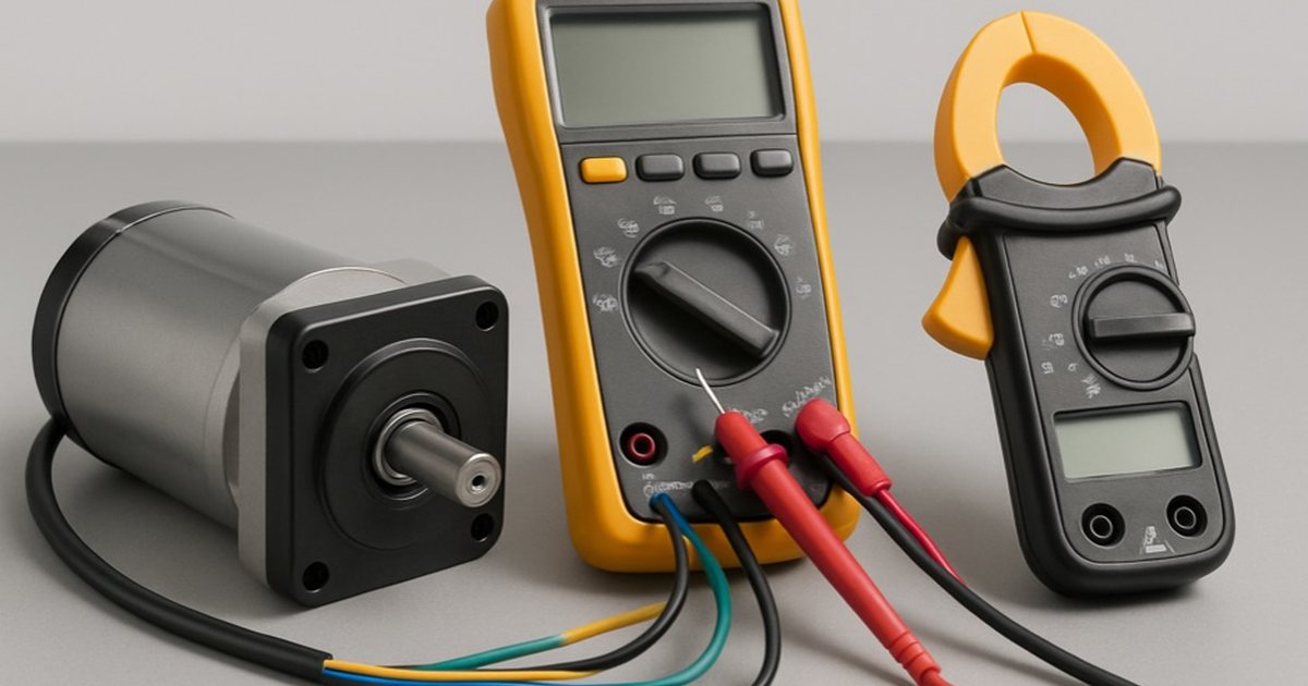
- Digital multimeter with a milliohm-capable resistance range — phase resistances are often below 1 Ω, so a meter that only resolves to 0.1 Ω will mislead you.
- Clamp meter with DC current capability. The single most useful tool for this work. An AC-only clamp is useless on a DC bus.
- Infrared thermometer for housing and controller heatsink temperatures.
- Insulation tester (megger), 500 V DC range — for suspected moisture ingress or winding-to-frame breakdown.
- Oscilloscope (optional but decisive for Hall timing and PWM problems).
Warning: never apply a 500 V megger test with the Hall sensors or controller connected. Hall ICs are rated for a few volts and will be destroyed instantly. Disconnect the Hall harness and the controller, then test the three phase leads to the motor housing only.
Baseline Measurements: What "Healthy" Looks Like
You cannot diagnose a motor without knowing what a good one reads. These are the ranges from our production test bench, measured phase-to-phase at 20°C on 48V windings.
| Frame | Power | Phase-to-phase R (48V winding) | Same frame, 24V winding | Back-EMF, brisk hand spin |
|---|---|---|---|---|
| BL42 / BL57 | 15–100 W | 2.0–8.0 Ω | 0.5–2.0 Ω | 1–3 V AC |
| BL60 | 100–200 W | 1.0–3.0 Ω | 0.25–0.75 Ω | 1–4 V AC |
| BL80 | 200–400 W | 0.4–1.5 Ω | 0.10–0.38 Ω | 2–5 V AC |
| BL90 | 400–600 W | 0.25–0.9 Ω | 0.06–0.23 Ω | 2–6 V AC |
| BL104 | 600–1,000 W | 0.15–0.6 Ω | 0.04–0.15 Ω | 3–7 V AC |
| BL120 | 1,000–2,000 W | 0.08–0.35 Ω | 0.02–0.09 Ω | 3–8 V AC |
| BL130 | 2,000–3,000 W | 0.05–0.20 Ω | — (48V/72V only) | 4–9 V AC |
Measured at 20°C. Copper resistance rises about 0.39% per °C, so a hot motor reads roughly 20% higher at 70°C — always compare like with like. The 24V column is approximately one quarter of the 48V value because the winding uses half the turns at twice the cross-section; see our 24V vs 48V bus voltage guide for why.
The three pass/fail rules that matter more than any absolute number:
- Phase balance: the three phase-to-phase readings must agree within 5%. Our factory QC limit is 3%. Above 10% means a shorted turn or a bad internal joint — the motor is not repairable in the field.
- Phase to housing: should read open circuit on a multimeter, and above 5 MΩ at 500 V DC per IEEE 43-2013 for low-voltage windings. A dry, healthy 48V winding normally reads well above 100 MΩ. Anything under 1 MΩ means moisture or insulation damage.
- Back-EMF balance: spin the shaft by hand and measure AC volts across each phase pair in turn. The three readings must be within 10% of each other. Unbalanced back-EMF with balanced resistance points to partially demagnetised rotor magnets — usually from a prior overheating event.
Hall sensor baseline
With 5 V applied to the Hall supply pin and the shaft turned slowly by hand, each of the three Hall outputs should switch cleanly between roughly 0 V and 5 V. Across one electrical revolution you should observe exactly six states, and you must never see 000 or 111 at any rotor position. Both of those are invalid and indicate a dead sensor, a broken signal wire, or a missing pull-up resistor (open-collector Hall ICs need a 1–10 kΩ pull-up to 5 V; most controllers provide it internally, but bench test rigs often do not). Our Hall sensor guide has the full commutation table and pin-by-pin wiring.
Looking for a reliable BLDC motor supplier? Get a sample motor shipped in 7 days.
Request a Quote →Symptom Triage Table
Start here. Find your symptom, then jump to the detailed fault section below.
| Symptom | Most likely cause | First test (60 seconds) |
|---|---|---|
| Completely dead, no sound or vibration | Supply, fuse or enable signal | Measure bus volts at controller terminals under load |
| Hums or twitches, will not rotate | Phase/Hall wiring, or jammed load | Disconnect load, try to turn the shaft by hand |
| Runs rough, cogs, draws high current | Wrong phase/Hall combination | Clamp-meter the DC current at no load |
| Turns one direction only | Hall sequence or direction input | Check DIR pin state and Hall order |
| Housing above 80°C | Overload or duty-cycle mismatch | Clamp-meter current vs nameplate rating |
| Overcurrent trip on acceleration only | Current limit set too low | Compare limit setting to 2–3× rated current |
| Overcurrent trip immediately on power-up | Shorted phase or shorted MOSFET | Phase-to-phase and phase-to-housing resistance |
| Speed hunts or oscillates | Controller PI tuning or noisy speed reference | Run open-loop; if stable, it is the loop |
| Growling or rumbling noise | Bearing wear or misalignment | Spin by hand with load removed, listen and feel |
| Low torque, motor stalls under load | Under-sized motor, low bus voltage, or wrong commutation | Measure current at stall vs rated |
| Motor will not turn, brake clicks | Electromagnetic brake not releasing | Measure brake coil voltage during run command |
| Erratic behaviour near contactors or VFDs | EMI on Hall or speed reference lines | Shield and separate signal cable from power cable |
Working through a fault on a live machine? Send us the motor model, the measured phase resistances and a photo of the wiring and our engineers will read it with you. Contact technical support →
Fault 1: Motor Will Not Start (Silent, No Vibration)
A completely silent motor is almost never a motor fault. Work the supply chain from the battery outwards:
- Bus voltage at the controller terminals, measured under load. Not at the battery. A 48V pack that reads 51 V open-circuit and collapses to 38 V when the run command is given has either an undersized cable, a corroded connector, a tired cell group or a BMS current limit cutting in. Most controllers assert undervoltage lockout at 80–85% of nominal (about 40 V on a 48V bus).
- Enable / brake / start input. Many industrial BLDC controllers use an active-low enable and will remain silent with the pin floating. Check the wiring diagram for your controller — this accounts for a surprising share of "dead on arrival" reports on new installations.
- Speed reference. A 0–5 V or potentiometer input sitting at 0 V is a valid "stop" command. Measure it.
- Fuse and contactor. Obvious, and worth 10 seconds.
- Motor winding continuity. Only now do you suspect the motor. An open phase reads infinite resistance on one of the three pairs.
Fault 2: Motor Hums or Jitters But Will Not Rotate
The controller is energising the windings, so power and enable are fine. Two candidates:
Mechanically jammed. Remove the run command, disconnect the load, and turn the output shaft by hand. A geared motor should turn with resistance but turn. If it will not, the fault is in the gearbox, the driven machine, or an engaged brake — not the motor.
Commutation cannot start. The controller does not know the rotor position, so it energises the wrong pair and the rotor oscillates in place. This is usually a Hall sensor with no supply (check 5 V at the Hall connector), a broken Hall signal wire (reading stuck at 0 V or 5 V through a full shaft rotation), or a sensorless controller attempting to start into a high-inertia or high-friction load, which is a known limitation of sensorless control at zero speed.
Fault 3: Motor Runs Rough, Cogs and Draws High Current
This is the classic symptom of a phase/Hall mismatch, and it is the fault we most often talk customers through by phone.
There are three phase wires (U, V, W) and three Hall signals (Ha, Hb, Hc). That gives 3! × 3! = 36 possible wiring permutations, of which only 6 commutate correctly. Several of the wrong 30 will still spin the motor — badly. The signature is unmistakable once you know it: the motor turns, but noisily and with visible torque ripple, it draws two to four times normal no-load current, it gets hot within a minute, and it produces perhaps 30–50% of rated torque.
| Combination | Phase order | Hall order |
|---|---|---|
| 1 | U V W | Ha Hb Hc |
| 2 | U V W | Hb Hc Ha |
| 3 | U V W | Hc Ha Hb |
| 4 | U W V | Ha Hc Hb |
| 5 | U W V | Hb Ha Hc |
| 6 | U W V | Hc Hb Ha |
Test each combination at no load and record the DC current draw with a clamp meter. The correct combination is the one with the lowest no-load current and the smoothest sound — typically 5–12% of rated current at no load.
Many modern controllers have an auto-learn or self-identification routine that walks these combinations for you in about 30 seconds. All of our BLDC controllers supplied with a matched motor are pre-configured at the factory, which is the main practical argument for buying the motor and controller as a set rather than sourcing them separately.
If the roughness survives all six combinations, the cause is elsewhere: partially demagnetised rotor magnets (check back-EMF balance), a Hall sensor that has drifted out of alignment mechanically, or damaged bearings.
Fault 4: Motor Runs in One Direction Only
Check the direction input first — a floating DIR pin defaults one way on most controllers. If the input toggles correctly and the motor still refuses to reverse, or reverses roughly while running smoothly forward, the Hall sequence is one of the "half-correct" permutations that happens to work in one rotation direction. Return to the six-combination table above.
Fault 5: Overheating
The field alarm threshold is a housing surface temperature above 80°C. The real limit is the winding hot-spot, governed by insulation class under IEC 60034-1:
| Insulation class | Max winding hot-spot | Typical housing surface at rated load | Used in |
|---|---|---|---|
| Class B | 130 °C | 55–70 °C | Cost-sensitive general purpose |
| Class F | 155 °C | 60–80 °C | Industry standard — our default |
| Class H | 180 °C | 70–95 °C | High ambient, enclosed or heavy-duty service |
Hot-spot limits per IEC 60034-1 at 40°C reference ambient. Every 10°C above the class limit roughly halves winding insulation life — the Arrhenius relationship that governs all thermal ageing in motors.
Work through the four causes in this order:
- Overload. Clamp-meter the DC bus current and compare it to the nameplate. If the motor is drawing 1.3× rated current continuously, it is being asked for 1.3× rated torque and it will overheat — no amount of cooling fixes an undersized motor. Recheck the sizing with our torque and power calculation guide.
- Duty-cycle mismatch. A motor rated for S1 continuous duty used in S3 or S5 intermittent service with frequent starts sees very high RMS current from the acceleration peaks even when average load looks modest. Every start of a high-inertia load dumps energy into the windings. Count the starts per hour, not just the average torque.
- Wrong commutation. Covered in Fault 3 — a mis-sequenced motor is inefficient and heats fast. Confirm no-load current is in the normal 5–12% band before blaming the load.
- No heat path. A BLDC motor sheds most of its heat through the mounting flange into the machine frame. Mounting on a plastic bracket, wrapping it in insulation, or enclosing it in a sealed box without airflow can add 20–30°C. Bolt the flange to metal.
Fault 6: Controller Overcurrent Trips
The timing of the trip tells you the cause:
| When it trips | Cause | Fix |
|---|---|---|
| During acceleration only | Current limit set near continuous rating | Raise the limit to 2–3× rated with a 1–3 s time window, or extend the ramp time |
| At steady speed under load | Genuine mechanical overload or drivetrain drag | Reduce load, check gearbox and bearings, or move up a power class |
| Immediately on power-up | Shorted phase, shorted output MOSFET, or phase touching housing | Disconnect motor and measure phase-to-phase and phase-to-housing |
| Randomly, no load correlation | EMI on the current-sense circuit, or a loose power connection arcing | Re-torque all power terminals, shield signal cables (see Fault 12) |
| Only on deceleration | Regenerative energy raising the bus voltage — often reported as overcurrent | Fit a braking resistor or extend the deceleration ramp |
Fault 7: Speed Instability and Hunting
If the speed oscillates around setpoint, run the drive in open loop. If it is stable open-loop, the fault is in the closed-loop control, not the motor: PI gains set too aggressive for the load inertia, or a speed reference signal polluted by noise. If it is unstable open-loop as well, look at bus voltage sag under load and at the Hall signal quality — a marginal Hall sensor produces intermittent position errors that show up as speed jitter.
A practical starting point for PI tuning on a high-inertia traction load: reduce proportional gain until the oscillation stops, then increase integral gain slowly until steady-state error is acceptable. High-inertia loads need lower proportional gain than the factory default, which is usually tuned for a low-inertia bench setup.
Fault 8: Noise and Vibration
Motor vibration is measurable, and IEC 60034-14 gives you a limit to measure against: for Grade A machines with shaft height up to 132 mm, free suspension, the limit is 1.6 mm/s RMS in the 600–3,600 rpm range. Beyond that number, the character of the noise tells you the source:
| Noise character | Likely source | Action |
|---|---|---|
| Dry rumble or growl, worse when warm | Bearing wear or grease breakdown | Replace bearings (6000/6200 series, sealed, C3 clearance) |
| Rhythmic click once per revolution | Bearing brinelling, or debris in the gearbox | Strip and inspect; brinelling comes from impact loads or press-fitting through the bearing |
| High-pitched whine that tracks speed | PWM switching frequency in the audible band | Raise controller PWM frequency above 16 kHz |
| Rough cogging at low speed | Commutation error (see Fault 3) | Verify phase/Hall combination |
| Whole-machine vibration at one speed | Structural resonance, not a motor fault | Shift the operating speed or stiffen the mounting |
| Gearbox chatter under reversing load | Excessive backlash | Planetary gearboxes hold 8–15 arcmin; worm and helical are looser |
Bearings are the only genuinely wear-limited part of a BLDC motor. We specify sealed 6000/6200-series bearings with an L10 life of 20,000 hours at rated radial load; in AGV and conveyor service, geared units typically run 20,000–40,000 hours before noise appears. If a bearing fails in under 5,000 hours, look for a cause: overhung load beyond the rated radial limit, shaft misalignment, or a coupling installed by hammering the shaft, which brinells the races immediately.
Fault 9: Low Torque Under Load
The motor runs, but stalls or slows badly when the machine is loaded. Three checks:
- Is the current reaching rated? If the motor stalls while drawing well under rated current, the controller is limiting it — check the current limit setting.
- Is the bus voltage holding? Torque falls with available voltage. A pack sagging from 48 V to 40 V under load has lost 17% of its speed capability, and the controller will limit current to protect against undervoltage.
- Is commutation correct? A mis-sequenced motor produces 30–50% of rated torque. This is the most commonly missed cause.
If all three pass, the motor is genuinely undersized for the application. Re-run the sizing calculation — for mobile equipment, our AGV motor sizing guide covers payload, gradient, rolling resistance and wheel diameter, and the usual fix is a higher gearbox ratio rather than a bigger motor.
Fault 10: Electromagnetic Brake Will Not Release
Motors fitted with a spring-applied electromagnetic brake are fail-safe: the spring clamps the rotor and the coil must be energised to release it. If the brake stays engaged, the motor will hum, draw heavy current and trip.
- Measure the brake coil voltage during a run command. Our brakes are 24 V DC; anything below about 21 V may not overcome the spring, and a common cause is powering the brake through a long, thin wire that drops several volts.
- Check the brake release timing. The controller should energise the brake 100–300 ms before commanding torque. Reversed sequencing makes the motor fight an engaged brake on every start.
- Check the air gap. Brake pads wear; as the gap grows, the coil can no longer pull the armature. Most brakes have an adjustable gap of 0.2–0.5 mm.
- Check the flyback diode. An open flyback across the brake coil lets the collapsing field arc the switching contacts, which eventually welds or destroys them.
Fault 11: Moisture and Contamination Failures
Motors on outdoor equipment — PV cleaning robots, agricultural machinery, gate operators — fail differently from indoor motors. IEC 60034-5 defines the IP protection ratings, and it is worth knowing what your rating actually promises:
| Rating | Protection | Suitable for | Not suitable for |
|---|---|---|---|
| IP54 | Dust-protected, splashing water | Indoor industrial, light outdoor with a cover | Direct rain, washdown |
| IP65 | Dust-tight, low-pressure water jets | Outdoor equipment, food-plant washdown | Immersion, high-pressure jets |
| IP67 | Dust-tight, 30 min immersion at 1 m | Flooded floors, harsh outdoor service | Continuous immersion |
The tell for moisture ingress is a phase-to-housing insulation resistance that has fallen below 1 MΩ. Sometimes a motor that has taken in condensation can be recovered by baking it at 80–90°C for 4–6 hours and re-testing; if the reading returns above 100 MΩ it is usually serviceable. If water has reached the Hall sensor PCB, the sensors will need replacing regardless. Note also that repeated heating and cooling cycles pump humid air in and out through the shaft seal — a motor that is switched on and off daily outdoors accumulates moisture faster than one that runs continuously.
Fault 12: EMI and Erratic Behaviour
Symptoms that appear only when a nearby contactor, VFD or welder operates are electromagnetic interference, not motor faults. IEC 61000-6-2 sets the immunity requirements for industrial environments; the practical countermeasures are:
- Route Hall sensor and speed reference cables at least 200 mm away from motor phase cables, and cross them at 90° where they must meet.
- Use shielded cable for Hall and encoder signals, with the shield grounded at the controller end only — grounding both ends creates a ground loop that makes things worse.
- Keep motor phase cables as short as practical and twist them together; long parallel runs act as antennas.
- Fit an RC snubber or flyback diode across every inductive load switched near the drive (contactors, solenoids, the brake coil).
- Bond the motor housing to the machine frame with a short, wide strap, not a thin wire.
What Actually Fails: Our Warranty Return Data
This is the distribution we see across motors returned to our factory for analysis. It is worth studying before you order a replacement motor, because the numbers say the motor usually is not the problem.
| Root cause | Share of returns | Repairable in the field? |
|---|---|---|
| Wiring / connector faults (miswire, loose crimp, chafed lead) | ~30% | Yes |
| Controller failure (MOSFET, capacitor, config) | ~22% | Replace controller |
| Application overload / thermal abuse | ~18% | Resize the drive |
| Hall sensor failure | ~12% | Yes — sensor board is replaceable |
| Bearing wear | ~9% | Yes |
| Winding failure (shorted turn, open phase) | ~5% | No — requires rewind |
| Brake, encoder, gearbox and other mechanical | ~4% | Component dependent |
Distribution from our own warranty and field-return analysis across AGV, conveyor, gate and cleaning-robot applications. Roughly half of all returned motors pass full bench testing with no fault found.
The pattern is consistent: the two largest categories — wiring and controller — account for over half of all failures, and neither requires a new motor. Before you order a replacement, spend 15 minutes on the baseline measurements at the top of this guide. If the phase resistances are balanced and the back-EMF is balanced, the motor is fine.
Preventive Maintenance Schedule
| Interval | Check | Pass criteria |
|---|---|---|
| Monthly | Housing temperature at rated load | Below 80°C surface |
| Monthly | Listen for bearing noise | No rumble or click |
| Quarterly | Re-torque power terminals and connectors | To the controller manufacturer's spec |
| Quarterly | Clamp-meter current at typical load | Within nameplate rating |
| Semi-annually | Phase-to-phase resistance balance | Within 5% |
| Semi-annually | Insulation resistance at 500 V DC | Above 5 MΩ (IEEE 43-2013) |
| Semi-annually | Gearbox oil / grease condition | No metal particles, no leak |
| Annually | Brake air gap and pad wear (if fitted) | 0.2–0.5 mm |
| Annually | Seal and cable gland integrity (IP-rated units) | No cracking or ingress |
Frequently Asked Questions
Why is my BLDC motor not starting?
Check four things in order: bus voltage at the controller terminals under load (a sagging supply is the most common cause), the enable/brake input (many controllers use active-low enable and stay silent with the pin floating), phase-to-phase resistance at the motor connector (three readings within 5%, no open circuit), and the Hall outputs while back-driving the shaft by hand (each should toggle 0–5 V; never all high or all low).
Why is my BLDC motor overheating?
A housing above 80°C means overload, duty-cycle mismatch, wrong commutation, or no heat path. Clamp-meter the actual current first — it takes 30 seconds and identifies overload immediately. If current is within rating, count the starts per hour (an S1-rated motor in S3 service overheats from acceleration peaks), then verify the phase/Hall sequence, then check that the mounting flange is bolted to metal.
What resistance should a healthy BLDC winding read?
It depends on frame and winding voltage: a 48V 750W BL104 motor reads 0.15–0.6 Ω phase-to-phase, a 48V 200W BL60 motor reads 1.0–3.0 Ω. The 24V winding of the same frame reads about a quarter of the 48V value. Balance matters more than the absolute number: the three readings must agree within 5% (our factory QC limit is 3%). Above 10% deviation indicates a shorted turn.
Why does my BLDC motor run rough or cog?
Almost always a phase/Hall mismatch. There are 36 possible wiring permutations and only 6 commutate correctly — several wrong ones still spin the motor, but roughly, at 2–4× normal no-load current and 30–50% of rated torque. Work through the six valid combinations and pick the one with the lowest no-load current, or use a controller with auto-learn.
Why does my controller keep tripping on overcurrent?
Trips during acceleration only mean the current limit is set too close to the continuous rating — traction needs 2–3× rated for 1–3 seconds. Trips at steady speed mean genuine mechanical overload. Trips immediately on power-up mean a shorted phase, a shorted output MOSFET, or a phase touching the housing — disconnect the motor and measure before looking for a software cause.
How long should a BLDC motor last?
The bearings are the wear-limited part. Our sealed 6000/6200-series bearings are specified for 20,000 hours L10 at rated radial load, and geared units in AGV or conveyor service typically run 20,000–40,000 hours before noise appears. Windings and magnets do not wear out — they fail only from thermal abuse, moisture or overvoltage. Operated within rating, a BLDC motor normally outlasts the machine.
Is the motor or the controller faulty?
Test the motor in isolation. Disconnect it and measure the three phase-to-phase resistances (balanced within 5%), then spin the shaft briskly by hand and measure AC volts between each phase pair (balanced within 10%, a few volts). If both pass, the motor is almost certainly good — roughly half of our warranty returns test perfectly, with the real fault in the harness, connector, controller or application load.
Can a demagnetised BLDC rotor be repaired?
Not economically. Partial demagnetisation shows up as unbalanced back-EMF with balanced winding resistance, and it is caused by a prior overheating event or a severe overcurrent. Re-magnetising requires removing the rotor and fixturing it in a magnetiser, which costs more than a new rotor assembly. The important step is finding the cause — a replacement motor in the same application will fail the same way.
Need Help Diagnosing a Motor Fault?
Send us the motor model, your measured phase resistances, the no-load current and a photo of the wiring. Our engineers will read the results with you and tell you whether the motor, the controller or the application is at fault — before you order anything.