
Every BLDC motor has two fundamental constants that define its electrical-mechanical conversion: the torque constant Kt (how much torque per amp) and the speed constant Kv (how much speed per volt). These two numbers, determined by the motor's winding design, control everything from current draw to cable sizing to battery life. Understanding them is essential for anyone specifying BLDC drive systems.
This guide explains Kt and Kv with real manufacturer data from our motor range, shows you how to calculate current draw from torque requirements, and covers the practical aspects of winding voltage selection and wire sizing that equipment designers need to get right.
Torque Constant (Kt): The Core of Motor Sizing
The torque constant Kt tells you how much electromagnetic torque the motor produces for each ampere of current flowing through the windings.
Torque (N.m) = Kt (N.m/A) x I (A)
Kt is a fixed property of the motor's electromagnetic design — determined by the number of stator poles, magnet strength (grade), air gap, winding turns, and stator geometry. It does not change with speed, voltage, or load (within the linear operating range).
Why Kt Matters for Motor Selection
- Current draw prediction — knowing Kt lets you calculate exactly how much current the motor draws at any torque point: I = T / Kt
- Controller sizing — the controller must handle the peak current at maximum torque. Controller current rating = Peak torque / Kt + no-load current + 20% margin
- Battery runtime — average current draw determines how long the battery lasts. Lower current (higher Kt or higher voltage) = longer runtime
- Cable and connector sizing — current determines wire gauge, connector rating, and heat generation in the wiring
Kt Values Across Our Motor Range
| Motor Frame | Power | Voltage | Rated Speed | Kt (N.m/A) | Rated Current | Rated Torque |
|---|---|---|---|---|---|---|
| BL-60 | 60W | 24V | 3,000 RPM | 0.064 | 3.0A | 0.19 N.m |
| BL-80 | 200W | 24V | 3,000 RPM | 0.073 | 9.2A | 0.64 N.m |
| BL-80 | 200W | 48V | 3,000 RPM | 0.146 | 4.6A | 0.64 N.m |
| BL-90 | 400W | 48V | 3,000 RPM | 0.152 | 9.0A | 1.27 N.m |
| BL-104 | 750W | 48V | 3,000 RPM | 0.159 | 16.5A | 2.39 N.m |
| BL-120 | 1,500W | 48V | 3,000 RPM | 0.167 | 33A | 4.77 N.m |
| BL-130 | 3,000W | 48V | 3,000 RPM | 0.178 | 65A | 9.55 N.m |
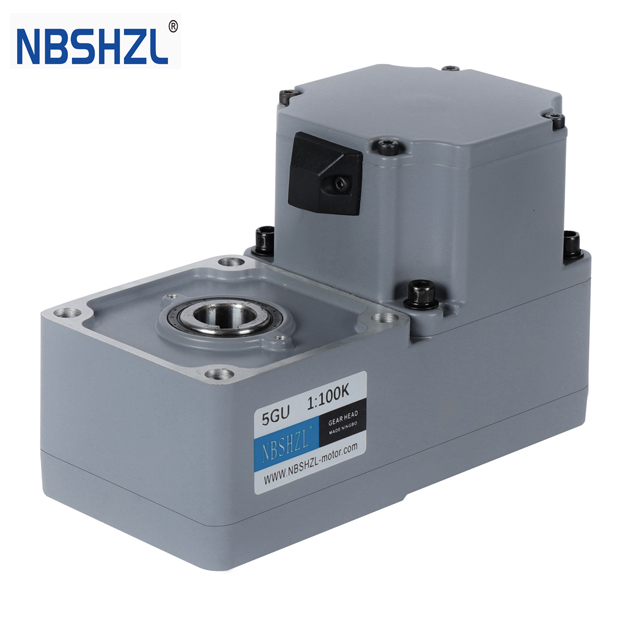
Notice that Kt increases with motor diameter. Larger motors have more magnet surface area and more stator slots, producing more flux linkage per ampere. This is why a 120mm motor is fundamentally more torque-dense than a 60mm motor — it is not just bigger, it is electromagnetically more efficient per unit of current.
Speed Constant (Kv): The Other Side of the Coin
Kv (RPM per volt) tells you how fast the motor spins per volt of back-EMF. It is the electrical reciprocal of Kt:
Kt (N.m/A) = 9.5488 / Kv (RPM/V)
Or equivalently: Kv = 9.5488 / Kt
This reciprocal relationship means you cannot independently choose Kt and Kv — they are two expressions of the same winding design. A motor wound for high torque per amp (high Kt) necessarily has low speed per volt (low Kv), and vice versa.
Practical Kv Ranges by Application
| Application | Typical Kv (RPM/V) | Typical Voltage | Why |
|---|---|---|---|
| Fan / blower drives | 100-200 | 12-24V | High speed, low torque |
| Pump drives | 80-150 | 24-48V | Moderate speed, moderate torque |
| Conveyor drives | 50-100 | 24-48V | Lower speed, higher torque |
| AGV / tug drives | 40-80 | 48V | Low speed, high torque (with gearbox) |
| Machinery movers | 30-60 | 48-72V | Very low speed, maximum torque |
For AGV and tug AGV drive systems, the motor's Kv is typically 40-80 RPM/V. Combined with a planetary gearbox (20:1-50:1 ratio), this produces the low wheel speed and high wheel torque these applications demand.
Need a BLDC motor with specific Kt/Kv values for your application? We can customize winding parameters.
Get a Custom Winding Quote →Winding Voltage: 24V vs 48V vs 72V
The same motor frame can be wound for different voltages by changing the number of wire turns and wire diameter. This is one of the most impactful customization options we offer — and one of the most misunderstood aspects of motor specification.
How Voltage Affects the Motor
A 48V winding has approximately twice the turns of a 24V winding, using thinner wire (since less current flows). The key insight: mechanical output stays the same. A 500W motor produces 500W whether wound for 24V or 48V. What changes is the current:
| Parameter | 24V Winding | 48V Winding | Impact |
|---|---|---|---|
| Rated power | 500W | 500W | Same |
| Rated current | ~22A | ~11A | Half the current at 48V |
| Kt | 0.08 N.m/A | 0.16 N.m/A | Double Kt at 48V |
| Kv | 119 RPM/V | 60 RPM/V | Half Kv at 48V |
| Cable losses (I2R) | 4x higher | 1x (baseline) | 48V is far more efficient in cables |
| Minimum wire gauge | 12 AWG | 16 AWG | Thinner, lighter, cheaper cable at 48V |
| Controller heat | Higher (MOSFET I2R) | Lower | Smaller heatsink at 48V |
The general rule: use the highest voltage your battery pack and controller support. For detailed voltage selection, read our 24V vs 48V BLDC motor comparison.
When to Use Which Voltage
- 12V — only for very small motors (under 60W) in automotive accessories or consumer products
- 24V — standard for 30-400W motors. Good for compact systems where battery simplicity matters (single 24V pack). Common in light AGVs, gate operators, small conveyors
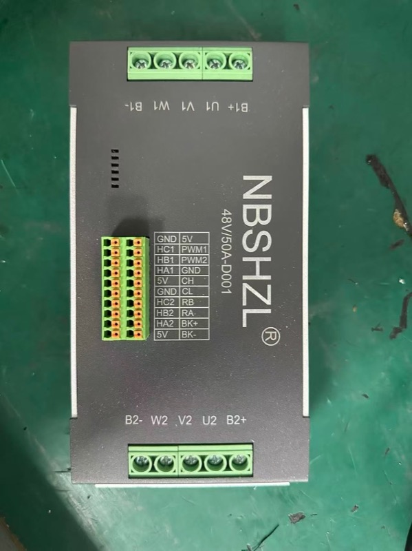
- 48V — standard for 200W-3kW motors. Preferred for AGVs, machinery movers, and any system above 400W. Cuts current in half vs 24V, enabling thinner cables and smaller controllers
- 72V — for high-power applications (1.5-3kW) where even 48V produces excessive current. Common in heavy-duty AGV tug systems and electric utility vehicles
Current Draw Calculation: From Torque to Amps
Once you know your required torque (from torque calculation) and the motor's Kt, calculating current is straightforward:
Imotor = Trequired / Kt + Ino-load
Worked Example: 5-Ton Tug AGV
From our tug AGV drive system guide, a 5-ton tug AGV on flat concrete needs approximately 1.27 N.m per motor at the motor shaft (after gearbox).
- Motor: BL-104, 750W, 48V, Kt = 0.159 N.m/A, Ino-load = 1.2A
- Continuous current: I = 1.27 / 0.159 + 1.2 = 9.2A per motor
- Peak current (slope + accel): I = 4.5 / 0.159 + 1.2 = 29.5A per motor
- DC bus current (both motors, FOC): 2 x 9.2 x 0.816 = 15.0A continuous from battery
Controller requirement: minimum 30A continuous per channel, 60A peak. Our dual-channel 48V/80A controller handles this with margin.
Wire Sizing Guide
Wire gauge must handle the continuous current without exceeding temperature limits and without excessive voltage drop. Here are our standard recommendations based on thousands of installations:
| Motor Power | Voltage | Typical Current | Wire Gauge (< 2m) | Wire Gauge (2-5m) | Connector |
|---|---|---|---|---|---|
| 30-100W | 24V | 1.5-5A | 20 AWG | 18 AWG | 4-pin M12 |
| 200-400W | 24V | 9-18A | 16 AWG | 14 AWG | 4-pin M16 |
| 200-400W | 48V | 5-9A | 18 AWG | 16 AWG | 4-pin M12 |
| 750W | 48V | 16-17A | 14 AWG | 12 AWG | 4-pin M16 |
| 1.5kW | 48V | 33A | 12 AWG | 10 AWG | Circular IP67 |
| 3kW | 48-72V | 42-65A | 10 AWG | 8 AWG | Heavy-duty IP67 |
Voltage drop rule: keep total cable voltage drop under 3% of bus voltage. For a 48V system, that means less than 1.44V drop across the full cable run (both directions). Voltage drop = I x Rcable x 2 (round trip). If the calculation exceeds 3%, go one gauge thicker.
Our pre-wired harness kits are sized correctly for each motor model with IP67 connectors, saving your assembly team from gauge calculations and crimping errors.
Custom Winding: What We Can Adjust
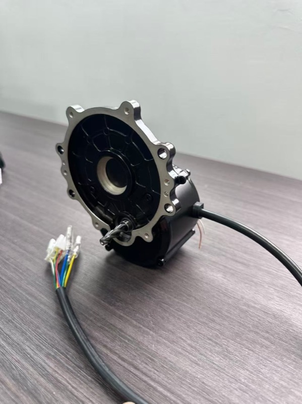
As a motor manufacturer, we can customize the winding for your specific voltage and speed requirements. Parameters we adjust:
- Voltage — any standard voltage from 12V to 220V DC (changes wire turns and gauge)
- Speed — adjusting turns/pole changes Kv and rated speed (1,000-4,000 RPM range)
- Torque constant — directly follows from voltage and speed selection
- Thermal class — Class B (130C), Class F (155C), or Class H (180C) insulation
- Wire termination — flying leads, PCB pins, quick-disconnect, or custom connector
Custom winding adds no tooling cost and no price premium at MOQ (50 units). The motor frame, magnets, bearings, and housing stay the same — only the winding changes. Typical lead time for a custom-wound motor sample: 7-10 days.
Efficiency and Copper Losses
The dominant loss mechanism in a BLDC motor at low-to-medium speed is copper loss (I2R heating in the windings). Understanding this helps optimize system efficiency:
Copper loss (W) = I2 x Rwinding
Where Rwinding is the phase-to-phase resistance. For our BL-104 (750W, 48V): R = 0.35 ohm, and at 16.5A rated current, copper loss = 16.52 x 0.35 = 95W. This represents 12.7% of rated power — the rest becomes useful mechanical output and iron/friction losses.
At partial load (typical for AGVs cruising on flat ground), current drops proportionally, and copper loss drops with the square of current. A motor drawing 8A instead of 16.5A has only 25% of the full-load copper loss. This is why BLDC motors maintain high efficiency across a wide operating range — and why slightly oversizing the motor (choosing 750W for a 400W application) actually improves system efficiency.
Frequently Asked Questions
What is the torque constant (Kt) of a BLDC motor?
Kt (N.m/A) defines how much torque a BLDC motor produces per ampere of current. For example, a motor with Kt = 0.15 N.m/A drawing 10A produces 1.5 N.m. Kt is the reciprocal of Kv: Kt = 9.5488 / Kv. It is determined by the motor's magnetic design and does not change with speed or load.
How do I calculate BLDC motor current draw from torque?
I (A) = Torque (N.m) / Kt (N.m/A) + I_no_load. For a motor with Kt = 0.15 N.m/A producing 3 N.m with 0.5A no-load current: I = 3/0.15 + 0.5 = 20.5A. DC bus current is Phase current x 0.816 for FOC or x 0.667 for trapezoidal commutation.
What is the relationship between Kv and Kt?
They are reciprocals: Kt = 9.5488 / Kv. A motor rated 100 RPM/V has Kt = 0.0955 N.m/A. You cannot independently set both — they are two expressions of the same winding design. High Kv = high speed, low torque per amp. Low Kv = low speed, high torque per amp.
How does winding voltage affect BLDC motor performance?
Same motor frame wound for 48V instead of 24V: double the turns, half the current, same mechanical output. 48V cuts cable losses by 75% (I2R), allows thinner wires, and reduces controller heat. Use the highest voltage your system supports.
What wire gauge do I need for my BLDC motor?
200-500W at 48V: 18-16 AWG. 750W at 48V: 14-12 AWG. 1.5-3kW at 48V: 12-10 AWG. For cable runs over 3m, go one gauge thicker. Keep total voltage drop under 3% of bus voltage.
Need a Custom Winding for Your Application?
Tell us your target voltage, speed and torque — our engineers will specify the optimal winding and provide a Kt/Kv datasheet within 24 hours. No tooling cost for custom windings at MOQ 50 units.