
A brake is the cheapest part of a drive system and the one most often specified from a single number on a datasheet. That is why we see the same three failures over and over: a brake sized against the wrong shaft, a brake wired with a bare flyback diode so it engages a third of a second late, and a control sequence that disables the motor before the brake has closed. All three let a machine move when it should be still. This guide covers the calculations and the wiring that prevent them.
Quick Answer
- Size at the motor shaft. Tbrake ≥ (Tload ÷ i) × 2 to 2.5. The gearbox has already divided the torque, so a 32 N.m wheel load behind 20:1 needs only a 4 N.m brake.
- Spring-applied, always. Power-off fail-safe holds when the battery dies, the fuse blows or the e-stop is hit. Power-applied brakes have no place on a vehicle.
- The flyback diode trap. A bare diode across the coil stretches engage time from 25–60 ms to 150–400 ms. Add a Zener or TVS in series. At 1 m/s that difference is 300 mm of unwanted travel.
- Sequence matters. Release brake → wait → enable motor. Stop motor → hold zero speed → engage brake → wait → disable motor.
- Never use it as a service brake. Millions of static engagements, but only 10,000–50,000 dynamic stops at rated energy.
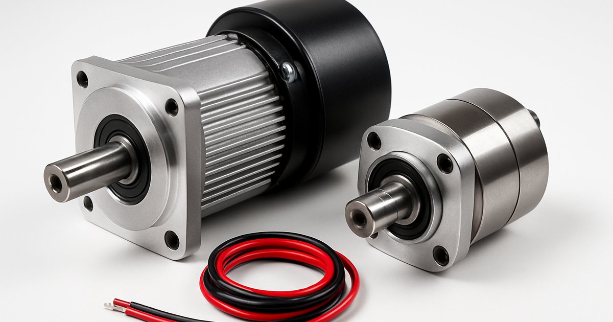
How a Spring-Applied Brake Works
A power-off electromagnetic brake has four parts: a coil in a steel housing, a set of compression springs, a movable armature plate and a friction disc splined to the motor shaft. With the coil de-energised, the springs push the armature against the friction disc and clamp it to the housing. Energise the coil and the magnetic field pulls the armature back against the springs, opening a small air gap and freeing the shaft.
That arrangement is why it is called fail-safe: holding is the default state, and releasing is the state that requires energy. Cut the wire, blow the fuse, flatten the battery or press the emergency stop and the brake closes on its own.
| Brake type | Holds when | Releases when | Use on a vehicle? |
|---|---|---|---|
| Spring-applied (power-off) | Unpowered | Coil energised | Yes — the only acceptable type |
| Power-applied (power-on) | Coil energised | Unpowered | No — releases on power loss |
| Permanent magnet | Unpowered (magnet) | Coil bucks the magnet | Yes, but narrow voltage window and higher cost |
| Self-locking worm gearbox | Depends on lead angle, temperature, vibration | n/a | No — not a diagnosable safety function |
All brakes in our drive system accessories range are 24 V DC spring-applied, in 2, 4, 8, 15, 25 and 40 N.m holding torques, mounted on the motor rear shaft.
Step 1: Size the Holding Torque at the Right Shaft
This is the mistake that costs the most money, because it usually goes the wrong way: someone calculates 32 N.m of load torque at the wheel and orders a 40 N.m brake, then finds it does not fit inside the vehicle and costs six times what it needed to.
A brake mounted on the motor rear shaft sits before the gearbox. The gearbox multiplies torque by the ratio, so the torque the brake must resist is the load torque divided by the ratio:
Tbrake ≥ (Tload ÷ i) × SF
Leave gearbox efficiency out of the divisor. When the load back-drives the gearbox, efficiency reduces the torque that reaches the motor shaft, so ignoring it makes your answer conservative by 10–15%. Use a safety factor SF of 2.0–2.5 for a static parking brake.
Worked example: 1.3 tonne AGV on a 5% grade
- Holding force on grade: F = m · g · sin θ = 1,300 × 9.81 × 0.05 = 638 N
- Two 200 mm drive wheels → 319 N each → Twheel = 319 × 0.100 = 31.9 N.m
- Behind a 20:1 gearbox: 31.9 ÷ 20 = 1.60 N.m at the motor shaft
- × 2.5 safety factor = 4.0 N.m → specify a 4 N.m brake
A 4 N.m brake costs roughly $40–$70 and adds 40 mm to the motor. The 40 N.m brake someone would have ordered from the wheel figure costs $180–$300 and adds 60 mm. Same holding performance. The sizing method behind the wheel torque figure is covered in our AGV drive wheel assembly guide.
| Load torque at output | Gear ratio | Reflected at motor | × 2.5 SF | Specify |
|---|---|---|---|---|
| 10 N.m | 10:1 | 1.00 N.m | 2.5 N.m | 4 N.m |
| 32 N.m | 20:1 | 1.60 N.m | 4.0 N.m | 4 N.m |
| 60 N.m | 20:1 | 3.00 N.m | 7.5 N.m | 8 N.m |
| 120 N.m | 30:1 | 4.00 N.m | 10.0 N.m | 15 N.m |
| 250 N.m | 40:1 | 6.25 N.m | 15.6 N.m | 25 N.m |
| 600 N.m | 40:1 | 15.0 N.m | 37.5 N.m | 40 N.m |
Specify column rounds up to our standard sizes. If the brake sits on the gearbox output shaft instead of the motor rear shaft, drop the gear ratio from the calculation entirely and size against the full load torque.
Not sure whether your brake belongs on the motor shaft or the output shaft? Send us your gearbox ratio and holding requirement and we will size it — use the drive selection form.
Looking for a reliable BLDC motor supplier? Get a sample motor shipped in 7 days.
Request a Quote →Step 2: Check Dynamic Energy, Not Just Torque
Holding torque only tells you whether a stationary load stays stationary. If the brake ever has to stop something that is moving — an emergency stop, a power failure, a controller fault — it also has to absorb kinetic energy as heat:
E = ½ · m · v² + ½ · J · ω²
The linear term dominates on vehicles; the rotational term matters on flywheel-like loads such as fans and centrifuges. Our 1.3 t AGV at 1.0 m/s carries 650 J. Multiply by back-drive efficiency (~0.85) and about 550 J actually reaches the brake disc.
| Brake size | Max energy per stop | Continuous friction power | Static engagements | Dynamic stops at rated energy |
|---|---|---|---|---|
| 2 N.m | ~600 J | ~40 W | > 5 million | ~10,000 |
| 4 N.m | ~1,000 J | ~60 W | > 5 million | ~15,000 |
| 8 N.m | ~2,000 J | ~90 W | > 5 million | ~20,000 |
| 15 N.m | ~4,000 J | ~150 W | > 5 million | ~30,000 |
| 25 N.m | ~7,000 J | ~220 W | > 5 million | ~40,000 |
| 40 N.m | ~11,000 J | ~320 W | > 5 million | ~50,000 |
Typical values across our brake range; exact figures are model dependent and appear on the individual datasheet. Dynamic stop counts assume rated energy per stop — at 25% of rated energy, expect roughly 4–6× the cycle count.
Read the two right-hand columns together. Static holding is essentially free; dynamic stopping is a consumable. A vehicle that stops mechanically 200 times per shift will chew through a brake in under a year. The same vehicle that decelerates electrically and then engages the brake at zero speed will still be on its original brake a decade later.
That is why the correct architecture is electrical braking first: the controller ramps the motor down under closed-loop control, dumping energy into the battery or a braking resistor, and the mechanical brake only holds. Controller selection for regenerative deceleration is covered in our BLDC motor controller selection guide.
Step 3: Coil Suppression — the Mistake That Costs You 300 mm
A brake coil is a large inductance. When the switching device opens, the collapsing field induces a voltage spike that will destroy an unprotected MOSFET, so everyone fits some form of suppression. The choice of suppression is where things go wrong, because the intuitive option is the worst one.
A plain flyback diode across the coil gives the current a lossless loop to circulate in. The field decays only as fast as the coil resistance dissipates it, which is slow — and until the field has decayed below the spring force, the armature stays pulled in and the brake has not engaged.
| Suppression method | Clamp voltage (24 V coil) | Engage time | Travel at 1 m/s | Verdict |
|---|---|---|---|---|
| Plain diode (1N4007) | ~24.7 V | 150–400 ms | 150–400 mm | Avoid on safety brakes |
| Diode + 36 V Zener in series | ~60 V | 25–60 ms | 25–60 mm | Recommended |
| Bidirectional TVS (SMBJ33CA) | ~53 V | 30–70 ms | 30–70 mm | Recommended |
| MOV / varistor 39 V | ~65 V | 30–80 ms | 30–80 mm | Acceptable; ages over time |
| RC snubber alone | Varies | 60–150 ms | 60–150 mm | Marginal |
| No suppression | > 400 V | 10–25 ms | 10–25 mm | Fastest, but destroys the switch |
Engage times measured on our test bench with a 4 N.m 24 V brake, switching on the DC side, coil at 20°C. Times increase 10–20% at a hot coil. Choose a clamp voltage the switching device can survive: a 100 V MOSFET is comfortable with a 60 V clamp.
The other half of the same issue is where you switch. If the brake runs from an AC supply through a rectifier and you switch on the AC side, the rectifier and its smoothing capacitor keep feeding the coil for another 100–300 ms after the contactor opens. Switch on the DC side, between rectifier and coil, and the difference disappears. On a 24 V battery vehicle this is moot — you are already on DC — but it catches out anyone adapting a mains-fed design.
Step 4: Get the Start and Stop Sequence Right
A brake and a motor that both do the right thing at the wrong time still produce a machine that moves when it should not. The sequence below is what we ship in our reference control logic.
Start sequence
- Verify safety chain is closed and no fault is latched
- Energise the brake coil (release)
- Wait release time + margin: 80–150 ms
- Enable the motor output and ramp to target speed
Enabling the motor into an engaged brake is a locked-rotor condition. The controller sees full current at zero back-EMF and trips overcurrent, typically within 50–200 ms. If a machine trips on startup roughly once in every twenty cycles, an inconsistent brake release delay is a prime suspect — see the overcurrent section of our BLDC motor troubleshooting guide.
Stop sequence
- Ramp the motor to zero speed under closed-loop control
- Hold zero-speed torque for 100–200 ms so the load is genuinely stationary
- De-energise the brake coil (engage)
- Wait engage time + margin: 80–150 ms
- Disable the motor output
Steps 2 and 4 are the ones that get deleted during a schedule crunch, and their absence is the classic cause of an AGV that creeps 100–300 mm backwards on a ramp every time it stops. The load is unsupported for the entire brake engage delay if you disable the motor first.
Emergency stop
An emergency stop must remove power from the brake coil through the safety circuit, independently of the motor controller — not by asking the controller to do it. ISO 13849-1 Performance Level d for the braking function normally means a dual-channel arrangement: two series safety contacts or relays with feedback monitoring, so a single welded contact cannot keep the brake released.
Step 5: Mechanical and Electrical Integration Details
| Brake torque | Coil power (24 V) | Coil current | Added motor length | Added mass | Manual release |
|---|---|---|---|---|---|
| 2 N.m | 8–12 W | 0.33–0.50 A | ~35 mm | 0.6 kg | Option |
| 4 N.m | 10–14 W | 0.42–0.58 A | ~40 mm | 0.9 kg | Option |
| 8 N.m | 14–18 W | 0.58–0.75 A | ~45 mm | 1.3 kg | Standard |
| 15 N.m | 18–24 W | 0.75–1.00 A | ~50 mm | 1.7 kg | Standard |
| 25 N.m | 22–28 W | 0.92–1.17 A | ~55 mm | 2.1 kg | Standard |
| 40 N.m | 26–32 W | 1.08–1.33 A | ~60 mm | 2.5 kg | Standard |
Coil power rises about 10% as the coil heats to steady state. On battery vehicles this is a real budget item: a 4 N.m brake at 12 W held released for a full 8-hour shift consumes about 96 Wh, roughly 2 Ah from a 48 V pack.
Three integration points worth writing into your specification:
- Manual release. A dead vehicle blocking an aisle has to be pushable. We fit a lever or screw release as standard on 8 N.m and above; ask explicitly on smaller units. ISO 3691-4 audits routinely check for it.
- Rotor inertia. The friction disc adds 10–30% to motor rotor inertia. On a traction axis that is irrelevant; on a high-bandwidth positioning axis it changes your tuning, so declare it to whoever writes the control loop.
- Ingress protection. The brake is usually the lowest-rated part of the assembly. An IP65 motor with an IP54 brake is an IP54 assembly. Specify a matched IP rating — per IEC 60034-5 — if the machine ever sees wash-down or outdoor conditions.
Maintenance: Air Gap Is the Whole Story
Almost every brake failure in service traces back to air gap. New, the gap between armature and friction disc is 0.2–0.4 mm. As the lining wears the gap grows, and magnetic force falls roughly with the square of the gap. Past about 0.6–0.8 mm the coil can no longer pull the armature reliably, and you get intermittent release failures, drag, heat and a burning smell.
| Symptom | Most likely cause | First check |
|---|---|---|
| Brake will not release; motor trips overcurrent | Air gap worn past limit, or coil undervoltage | Measure gap with feeler gauge; measure coil voltage at the brake under load |
| Brake releases but drags; housing hot | Partial release from voltage drop in long cable | Voltage at brake terminals ≥ 90% of nominal (21.6 V on a 24 V coil) |
| Load creeps after stop | Slow engage from flyback diode, or sequence error | Scope the coil current decay; verify motor is disabled after brake, not before |
| Squeal on engagement | Contaminated lining (oil, PU dust) | Inspect disc; replace, do not clean with solvent |
| Holding torque below spec | Glazed lining from repeated dynamic stops | Count dynamic stops per shift against the rating table above |
| Coil burnt out | Missing or failed suppression; overvoltage | Check clamp device; verify supply is 24 V DC not 24 V AC |
Recommended interval: inspect air gap and lining every 6 months or 2,000 operating hours, whichever comes first. Units below 8 N.m are generally sealed and replaced rather than shimmed.
One field note that saves a lot of arguments: measure coil voltage at the brake terminals, not at the supply. A 24 V brake at the end of a 4 m harness of 22 AWG drawing 0.6 A loses about 0.8 V, which is survivable; the same run in 26 AWG loses over 2 V and the brake will release only when cold and only sometimes.
Standards and Compliance
- ISO 3691-4 (driverless industrial trucks, 2020, amended 2023) — braking system safety function at PL d, parking brake function at PL b, per ISO 13849-1.
- ISO 13849-1 — defines the performance levels, and therefore the dual-channel, diagnosed brake control architecture required to reach PL d.
- EN ISO 13850 — emergency stop function; the brake must be part of the stop category implemented.
- ANSI/ITSDF B56.5 — North American equivalent for driverless automatic guided industrial vehicles.
- IEC 60034-5 — IP code for the motor-brake assembly.
- IEC 60204-1 — electrical equipment of machines; covers stop categories 0, 1 and 2 and where each is appropriate.
In practice the question an assessor asks is simple: can a single fault — one welded relay contact, one broken wire, one shorted transistor — leave the brake released when the safety function has demanded it closed? If the answer is yes, the architecture fails PL d regardless of how good the brake itself is.
What Brakes Cost
| Holding torque | Typical application | Price (FOB Ningbo, MOQ 50–100) | Manual release option |
|---|---|---|---|
| 2 N.m | Light AGV ≤ 300 kg, small conveyors | $30–$50 | +$8–$14 |
| 4 N.m | 1–1.5 t AGV drive units | $40–$70 | +$10–$16 |
| 8 N.m | 2–3 t AGV, machinery movers | $60–$100 | Included |
| 15 N.m | Heavy tuggers, lift axes | $90–$150 | Included |
| 25 N.m | 5 t+ platforms, hoists | $130–$220 | Included |
| 40 N.m | Output-shaft mounting, heavy hoists | $180–$300 | Included |
Prices as of September 2026, factory direct, fitted to the motor at assembly. Retrofitting a brake to a motor already in the field costs 2–3× more than specifying it at order time because the rear shaft, endbell and cable gland all change. Full drive pricing is in our BLDC motor price guide.
Frequently Asked Questions
How do I size an electromagnetic brake for a BLDC motor?
Size it at the motor shaft, not the load. Take the load holding torque, divide by gear ratio, apply a 2.0–2.5× safety factor. Example: a 1,300 kg AGV on a 5% grade needs 638 N of holding force, 31.9 N.m per 200 mm wheel, 1.6 N.m at the motor behind 20:1, so specify 4 N.m. Leave gearbox efficiency out of the divisor — it makes the answer conservative. If the brake must also stop a moving load, size for dynamic torque, typically 2–4× the static requirement.
What is a fail-safe electromagnetic brake?
A spring-applied, power-off brake: compression springs clamp the friction disc by default and the coil must be energised to release. Any loss of power — e-stop, blown fuse, flat battery, broken wire — engages it automatically. The opposite type, power-applied, releases on power loss and is unacceptable on vehicles or vertical axes. ISO 3691-4 effectively mandates fail-safe for driverless trucks, with the parking brake at PL b and the braking system at PL d under ISO 13849-1.
Why does my motor brake engage too slowly?
Nearly always a plain flyback diode across the coil, which lets current circulate so the field decays slowly and the armature stays pulled in. A 24 V brake that engages in 25–60 ms with proper suppression takes 150–400 ms with a bare 1N4007 — at 1 m/s, 300 ms is 300 mm of extra roll. Fix it with a Zener or TVS in series with the diode (36–47 V for a 24 V coil), or a bidirectional TVS alone, so coil energy dissipates at a controlled clamp voltage. Also switch on the DC side of any rectifier, not the AC side.
Can I use an electromagnetic brake to stop a moving load?
Occasionally, not routinely. A parking brake handles millions of static engagements but only 10,000–50,000 dynamic stops at rated energy. Use electrical braking as the service brake — the controller decelerates under closed-loop control into the battery or a braking resistor — and engage the mechanical brake at zero speed to hold. Reserve dynamic braking for emergency stops. Check energy per stop: a 1,300 kg vehicle at 1 m/s carries 650 J, within a 4 N.m brake's ~1,000 J rating but not every few seconds.
In what order should I release the brake and enable the motor?
On start: energise the coil to release, wait release time plus margin (80–150 ms), then enable the motor. Enabling into an engaged brake is a locked-rotor condition and usually trips overcurrent in 50–200 ms. On stop: decelerate to zero speed, hold zero-speed torque 100–200 ms, de-energise the coil, wait engage time plus margin, then disable the motor. Cutting motor and brake together lets the load roll during the engage delay — the usual cause of AGVs creeping backwards on ramps.
How much does a BLDC motor brake add in size, weight and cost?
A rear-mounted spring-applied brake adds 35–60 mm of motor length, 0.6–2.5 kg of mass and 10–30% to rotor inertia. FOB Ningbo at MOQ 50–100: about $30–$50 for 2 N.m, $40–$70 for 4 N.m, $60–$100 for 8 N.m, $90–$150 for 15 N.m, $130–$220 for 25 N.m, $180–$300 for 40 N.m; manual release adds $8–$20 on small sizes. Coil consumption is 8–30 W, so a 4 N.m brake held released for an 8-hour shift draws about 2 Ah from a 48 V pack.
What air gap should a motor brake have and when does it need service?
Nominal gap when new is 0.2–0.4 mm on brakes up to 40 N.m. As lining wears the gap grows and magnetic force falls roughly with the square of the gap; past 0.6–0.8 mm the coil cannot pull the armature reliably, causing intermittent release failures, drag and heat. Check with a feeler gauge every 6 months or 2,000 operating hours. Larger units can be shimmed; below about 8 N.m most are sealed and replaced.
Does a self-locking worm gearbox replace the need for a brake?
No, and safety assessors reject it. Self-locking depends on lead angle, lubricant viscosity, temperature and vibration, and degrades as the worm wears — and vibration, which defeats it, is exactly what a moving vehicle provides. It is a mechanical tendency, not a diagnosed and monitored safety function, so it cannot satisfy the PL b parking brake requirement of ISO 3691-4 via ISO 13849-1. Use a planetary or helical-bevel gearbox with a real spring-applied brake.
Need a Motor with the Right Brake on It?
Tell us the load torque, gear ratio, gradient and whether the brake ever has to stop motion rather than only hold it. We will size the brake, specify the suppression circuit and quote the complete motor-gearbox-brake assembly. MOQ 50 pcs, samples in 7–10 days.